There is more to life with TurboRenault.co.uk

Register a free account today to become a member! Once signed in, you'll be able to participate on this site by adding your own topics and posts, as well as connect with other members through your own private inbox!

21 Turbo Amrits Red Rocket

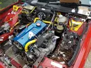
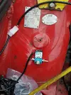
Then I decided to look at the fuel circuit. Simple enough and the rail already has AN6 fittings as did the reg input. Changed the pipes about a bit and mocked it up. Made a bracket to sit the reg on but didn't have the right bolts for it. They're tiny, I think M4. Zip ties for now then lol
20160806_175413.webp 20160806_175418.webp 20160806_175422.webp 20160806_175422.webp
 
Then a bit more wiring. Coolant sensor and MAT sensor, extended the coolant sensor wire in the middle so the right colour wire is at each end. Ran some more wire back to the +5v sensor feed from the ECU.
Fairly mundane solder/heatshrink pics :-) 20160806_184343.webp 20160806_184359.webp 20160806_184500.webp
 
Dave, I know you are just trial fitting the pressure reg But when I first fitted out the car I place the reg in a similar location and soon found the vibrations from the engine fractured the unions so I mounted the support to the ABS relay box.
 
Dave, I know you are just trial fitting the pressure reg But when I first fitted out the car I place the reg in a similar location and soon found the vibrations from the engine fractured the unions so I mounted the support to the ABS relay box.
Oh did they now? Hmmm, i'll have a rethink then. Cheers!
 
When your wiring are you labelling the plugs?
I've seen people use a dymo label maker to print names such as iscv then cover them with clear heat shink to keep them in place and clean.
Looks really smart too
 
When your wiring are you labelling the plugs?
I've seen people use a dymo label maker to print names such as iscv then cover them with clear heat shink to keep them in place and clean.
Looks really smart too
I am but only with masking tape for guidance when i'm making it. The Adaptronic loom is fully colour coded and where I need to extend a wire I am adding in the middle so the ends remain the right colours. I also have some notes for future ref, like "Inj power +12v Yellow, Sensor +5v split Orange".
Good idea that though, maybe try that in the future.
 
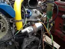
We decided to go with a PWM stepper type idle valve (phase 3) instead of the rotary phase one type because the rotary one takes up two pwm Aux outputs from the ECU to run. However noticing Mark Davis' idle valve on his thread I found that its a two wire type, but with a body shape like the rotary. I picked up a brand new one for a steal, the inlet is 90° off but a silicon bend will see it right. Well worth it to just be able to bolt it in the standard spot with the OE bracket.
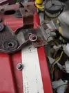
Someone had snapped both the studs off and the old valve was zip tied on so I fixed it properly. The studs just knock out and I bolted the new valve in roughly and wired it in.
20160821_115454.webp
20160821_175242.webp
 
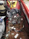
Then it was routing wiring, cutting lengths, crimping terminals and making up plugs for the CAS, TPS, MAC valve, and hard wiring in the power for injectors...stuff like that. I also got one of the power terminals I saw on nigels 225-19 thread and threw that in a rough position to hold the wiring in place.
20160821_175250.webp 20160821_175246.webp 20160821_175230.webp
 
Dave, where have you been sourcing those plugs please?

I have a perfectly serviceable wasted spark unit from my fiesta and was thinking about using that on Dan’s quadra. On the old coil pack you have two leads (apart from power and ground) one goes to the ECU and the other to the tacho. Not put a scope on these yet but how are you going to feed the tacho and are you using the same trigger input from the ECU?
Dan’s Ol’ Man

PS when soldering wires together - make sure they are WELL supported as the wire will fracture at the edge of the solder. If you are going to use in an area where there could be a lot of movement i.e. unsupported then use a crimp connector as these are less prone to wire fracture. Good use of adhesive heat shrink though!
 
Dave, where have you been sourcing those plugs please?
All the new plugs have come from EFI Parts website. The standard 2-pin one fits injectors and sensors nicely.
Not put a scope on these yet but how are you going to feed the tacho and are you using the same trigger input from the ECU?
Dans car is dizzy at the minute right? First off make sure the coils have a built in igniter, you MUST NOT wire the ECU direct. The VW coil EFI sell (as shown above) is ideal as he supplies the plug too.
I'm going to feed the tacho from IGN3 (IGN1&2 firing the 2 coils obviously), although this hasnt worked for Chris when he did the last installs - we dont know why - and he had to leave the OE coil in place too, fire that from IGN3 and let that drive the tacho. I will update when I get it working with either strategy.
One the OE setup the 3-pin plug is power/earth and FIRE signal, the twin plug with one wire is the tacho output.

Lastly the dizzy flywheel has 2 reset points, I think you will need a single reset one from a dizzyless or a 36-1 trigger wheel. The ECU cant tell which is cylinder 1 if you use a 2-reset flywheel with coil packs.
 
Lastly the dizzy flywheel has 2 reset points, I think you will need a single reset one from a dizzyless or a 36-1 trigger wheel. The ECU cant tell which is cylinder 1 if you use a 2-reset flywheel with coil packs.

Luckily a front pulley with a 36-1 is already made up along with a bracket and sensor so we can switch to using that pretty easily.
 
Back
Top