There is more to life with TurboRenault.co.uk
You are using an out of date browser. It may not display this or other websites correctly.
You should upgrade or use an alternative browser.
You should upgrade or use an alternative browser.
Alpine A610 Turbo - Megasquirt Conversion
- Thread starter r5gordini
- Start date
-
- Tags
- conversion turbo
DaveL485
Staff member
DaveL485
Staff member
MAP sensor has similar issues, hence transient throttle (MAP prediction) settings. The pressure wave travelling through the throttle to the intake ports moves at the speed of sound, so the engine needs fuel immediately when you snap the throttle open, and can't wait for the MAP sensor to react.can't react fast enough
D
Deleted member 486
I run closed for low load, open for heavy load...it seems to be the best route by general consensus/how Chris set it up/how he seems to set them all up. I can't tell you why specifically, might be worth looking into.
Generally it's a combination of factors some of which hark back to narrow band sensors so the maps would traditionally have to be open loop as the control just wasn't there and people have just carried on that way. Predominantly though it's due to the fuelling at high load being there for cooling so it doesn't actually need the lambda sensor per se - they are really only needed to control to lambda 1 although running lean at part load isn't an issue as long as you can control NOx (the big reason that OEMs don't do it) and your temperatures.
As you say, there needs to be a transient overfuelling capability as well as the sensors cannot react fast enough to prevent lean running when you quickly open the throttle blade.
Also, petrol engines generally produce maximum power at an AFR of ~12.5:1. In modern production cars performance enrichment is specifically banned so it has to be done as "component protection".
In all honest the best way to map for fuelling is to run an exhaust gas temperature probe(s) in conjunction with the lambda sensor. Then at part load you control to lambda 1 or a set temperature (with overfuelling to cool down), and then as you head towards WOT you switch to running the richest of either max fuel for best torque or the set temperature required for cooling.
Now finding that set temperature is a tricky one. You somehow need to correlate the exhaust gas temperature at your probe back to the temperature in the exhaust ports / pre-turbine and then find out the safe temperature for those components! Again, when an engine is in development we run temperature probes next to the valves, directly before the turbine, straight after the turbine, at the entry to the catalyst, mid-catalyst and catalyst exit. Then we control the fuelling to keep all of those below their maximum temperature threshold - generally 850/950°C but can be 1030°C on certain engines.
niconkk
Member
Crank sensor MUST be a shielded/screened cable. Don't just run [a wire] with other wires.
View attachment 19223
this one works... and its perfect por megasquirt pin size 0.8mm wire
Alpha Wire 5382C 18/1P XtraGuard 1 Premium Shield Twist Pair Control Cable /20ft | eBay
some protection for oil and up to 120 celcius, so its quite good for the engine bay
r5gordini
Well-Known Member
By way of an update as it's been a while!
- I wired up the evap canister solenoid to one of the stepper motor outputs - repurposing it
- I wired up the boost solenoid (Amal) valve in the same fashion as above. Unfortunately, it didn't seem to be very reliable and I broke one of the ports off while fiddling with it! I found a spare one I had in stock and refitted it. It's not much better. May end up buying something new and better. Given a tap, it seems to work fine and the original one looked perfect inside. I suspect they're just not very good. I hope that, when in a running car, the extra voltage and vibration will mean it works. The old Amal valve worked fine before I started the installation (or at least I believe it did)!
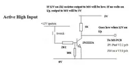
- Wired up the Air Con request... That was a bit of a pain. I had to construct a circuit to turn the +12v trigger from the OE switch into a pull-down to zero volts operation - requiring a transistor, diode and resistor, as per this circuit:
- Wired up an output to switch on the AC compressor relay - was a simple transistor circuit
- Then found I had a problem with the fans. The fans are supposed to come on at medium speed along with the AC compressor. Unfortunately, I was getting backfeeding of some sort, whereby the fans would come on regardless and would keep the MegaSquirt powered up even though the ignition was off! I partially fixed it by fitting a diode in the feed to the relay coil and then had a heart-stopping moment (nay, day) when the heating blower fan just stopped working altogether. I unplugged its connector and replugged it and it worked fine. Something to watch for the future, but it was very, very, very stressful as I tried to troubleshoot it. The manuals are not comprehensive enough to show how everything works! Even though I fitted a diode in the coil feed, it still didn't work properly, with the fans coming on with the key in the accessories position. I finally fixed it by completely isolating the coil feed for the relay with another relay, energised from the fuel pump relay (or the ECU relay - I can't remember which)!
- Then I started the laborious task of putting everything back together. I have significantly tidied up the wiring for the coils - it was a mess before! I had to remake some of the connections due to horribly tangled wiring. Matching up the physical installation with the actual wiring is one of the more challenging aspects of this installation
- The hoses for the map sensor, boost solenoid, etc., are really tightly packed in. I'm not terribly happy with their locations but they will have to do. I replaced all the hoses with generic hose but I went for reinforced fuel hose, which is a bit less flexible than the original stuff, so things are bit tight in places. Might need to relocate some hose clips as well to reduce the risk of chafing
- Wired up the engine bay fans. Interestingly, the original temp switch for them didn't route through a relay. I chose to add one and use lightweight wire to trigger that rather than running full current for the fans through the switch and loom. Wired up, tested, working, result! Interestingly, the right hand fan is the same as the GT Turbo Anti-perc fan. I pulled it apart a bit and lubricated it. Now running very nicely
- I'm really worried about the O2 sensor positioning. Unfortunately I chose a non-ideal placement for it - it's actually touching the left-hand exhaust manifold. BUT... through some extra heat insulation. It's already heat insulated but I added some high temperature heat sleeving. I hope it's enough. I think I might try it until it fails. If that happens I'll just loose the closed loop fuelling until I can get a new O2 sensor bung welded into somewhere more appropriate!
- The aux water pump wouldn't work. Argh! Unfortunately I discovered that after everything above it was fitted. Access is possible from beneath but it requires arms with at least 4 elbows to be able to get to it to undo the mounting. I eventually managed to flick the bracket open without needing to undo it. I tested the pump but couldn't get it to work. I pulled it apart to check and all looked OK, if a bit cruddy. I cleaned it up and then found the source of the problem - corroded connector terminals! After cleaning them and cleaning the terminals the other end it worked fine. I reassembled the pump with new screws. The originals were very dodgy. In fact, one broke off in the pump. I figured three out of four was ok
- Now just need to put everything else back together in order that I can drive the car. There's so much heat shielding it's ridiculous!
tutuur
Well-Known Member
A few niggles there but i see you should be able to manage!
I had the same problem when i wired in my boost solenoid. Didn't have it on a switched live so the engine kept running.... problem with fans is you wan't them constantly powered due to afterrun. On my F7r MS did nothing with the fan though, just left that part of the loom as standard.
I had the same problem when i wired in my boost solenoid. Didn't have it on a switched live so the engine kept running.... problem with fans is you wan't them constantly powered due to afterrun. On my F7r MS did nothing with the fan though, just left that part of the loom as standard.
r5gordini
Well-Known Member
Thank you! I've still got a couple of other major obstacles to overcome:
The fuel hose inlet for the right-hand fuel rail is hanging in mid air with no support. This is because of the necessary adapters I had to fit mean that it is angled up and away from the OE bracket. I'm rather nervous about leaving it like that in case it puts to much strain on the hose and it fails:
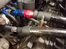
The thread on the OE bracket isn't long enough for the clamp to go over and clamp it down, even with a spacer underneath the hose. I'm trying to think of a way of extending the thread or modifying the bracket in some way. Any ideas, people?
And secondly, refitting the heat shield over the de-cat pipe on the LHS of the engine bay is going to be a pain. There are two bolts into the rear crossmember behind the bumper. Both have sheared off! They are enough to locate the heat shield but not to hold it, so I think I am going to drill a brand new hole and use a single rivnut to hold it and use the OE bolts to locate it. Or I may need two rivnuts...
I've also got to refit one of the multi-way connectors - down by the alternator, but I can't find the new stainless bolts and nuts I bought specifically for the job!
And tidy up the wiring for the trigger sensor...
And refit the turbo heatshields after trying again to reseat one of the exhaust manifold to turbo clamps.
And so it goes!
At some point I might want to get some custom HT leads made up but I want to avoid that expense right now.
The fuel hose inlet for the right-hand fuel rail is hanging in mid air with no support. This is because of the necessary adapters I had to fit mean that it is angled up and away from the OE bracket. I'm rather nervous about leaving it like that in case it puts to much strain on the hose and it fails:

The thread on the OE bracket isn't long enough for the clamp to go over and clamp it down, even with a spacer underneath the hose. I'm trying to think of a way of extending the thread or modifying the bracket in some way. Any ideas, people?
And secondly, refitting the heat shield over the de-cat pipe on the LHS of the engine bay is going to be a pain. There are two bolts into the rear crossmember behind the bumper. Both have sheared off! They are enough to locate the heat shield but not to hold it, so I think I am going to drill a brand new hole and use a single rivnut to hold it and use the OE bolts to locate it. Or I may need two rivnuts...
I've also got to refit one of the multi-way connectors - down by the alternator, but I can't find the new stainless bolts and nuts I bought specifically for the job!
And tidy up the wiring for the trigger sensor...
And refit the turbo heatshields after trying again to reseat one of the exhaust manifold to turbo clamps.
And so it goes!
At some point I might want to get some custom HT leads made up but I want to avoid that expense right now.
r5gordini
Well-Known Member
And thanks for the point on the fans - the A610 has a complicated arrangement where the fans can be triggered in so many different ways. I gave up with studying the wiring diagram and trying to figure out which relay triggers which and so on! There are relays for three different speeds... And there are relays which trigger relays which...
So I decided to leave the OE scheme well alone but prevent the MS from "interfering" with it.
I really did have one truly awful day, where I thought I'd caused serious damage to the HVAC system. Apparently there's a computer somewhere that controls the heater. I'll be blowed (see what I did there!) if I could find it! The blower fan just stopped working after I'd been messing with relays and diodes, etc.. I was wondering what I'd have to pull apart and fix. In the end I unplugged a connector as part of my troubleshooting and it suddenly sprang into life. Plugged it back in and it has worked perfectly since! No idea how or why but I'm trying not to worry about it... My current connection scheme avoids any sort of interference with it anyway as the relay I wired in the other day isolates the MS from the heating system.
I have one other major hurdle to overcome... The mess of the wiring where the ECU sits!
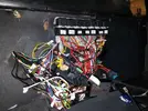
The challenge is that I had to add so many extra little modules, relays and fuses... It looks extra messy at the moment because nothing is tied down. I intend to start putting in some strategically placed cable ties to try and tidy it up a bit. Luckily everything is "soft" around that part of the loom. There's nothing that will chafe the wires, so they can stay exposed. They will be behind trim panels eventually.
There are also lots of wires from the OE loom that are no longer required. I need to insulate them all and tidy them up too. I will leave them labelled. One really nice thing with the OE loom is that each of the wires is individually numbered. The numbers are printed on the insulation! I wish I'd been able to replicate that with my own loom, but there you go... I have tried to be consistent with my wiring scheme and keep same colour running through the loom for each component.
Oh - I did a few other things too, including:
So I decided to leave the OE scheme well alone but prevent the MS from "interfering" with it.
I really did have one truly awful day, where I thought I'd caused serious damage to the HVAC system. Apparently there's a computer somewhere that controls the heater. I'll be blowed (see what I did there!) if I could find it! The blower fan just stopped working after I'd been messing with relays and diodes, etc.. I was wondering what I'd have to pull apart and fix. In the end I unplugged a connector as part of my troubleshooting and it suddenly sprang into life. Plugged it back in and it has worked perfectly since! No idea how or why but I'm trying not to worry about it... My current connection scheme avoids any sort of interference with it anyway as the relay I wired in the other day isolates the MS from the heating system.
I have one other major hurdle to overcome... The mess of the wiring where the ECU sits!

The challenge is that I had to add so many extra little modules, relays and fuses... It looks extra messy at the moment because nothing is tied down. I intend to start putting in some strategically placed cable ties to try and tidy it up a bit. Luckily everything is "soft" around that part of the loom. There's nothing that will chafe the wires, so they can stay exposed. They will be behind trim panels eventually.
There are also lots of wires from the OE loom that are no longer required. I need to insulate them all and tidy them up too. I will leave them labelled. One really nice thing with the OE loom is that each of the wires is individually numbered. The numbers are printed on the insulation! I wish I'd been able to replicate that with my own loom, but there you go... I have tried to be consistent with my wiring scheme and keep same colour running through the loom for each component.
Oh - I did a few other things too, including:
- I had to add another connector to the MS as I ran out of pins on the 37 way connector!
- Wired up the knock detector - one detector per bank. Digital on/off input into the MS
- Filled and bled the coolant system
- A while back, I fitted an inline fuse to the fuel pump feed. OE was unfused as far as I could tell!
DaveL485
Staff member
MAC valve would be better. The aftermarket ECU's run PWM at different frequencies I think, 25hz or 50hz (usually configurable), the OE amal valve runs (should run) at 12hz.The old Amal valve worked fine before I started the installation (or at least I believe it did)!
Upside-down p-clip trapped between 2 flange nuts, with another right way up p-clip for the other side.Any ideas, people?
r5gordini
Well-Known Member
Thanks Dave! I'll take a look at the P-clip idea.
I'm running the Amal valve at 11.1 Hz. I can run it at 11.1 Hz, 13Hz or 15Hz, and many more...
I think upgrading to a MAC valve is a good idea all round. It might also solve some of my space issues with some of the hoses being very close to each other around the area of the Amal valve. I'll get it on the road as is and then think again.
Andrew
r5gordini
Well-Known Member
I actually had another idea. I have removed the bracket and I think I can extend it by cutting and shutting it! If my welding will doUpside-down p-clip trapped between 2 flange nuts, with another right way up p-clip for the other side.
Here's the bit I need to cut and shut to make it a bit taller:

Even removing that was a challenge! It was bolted to the rocker cover and thus covered with so many pipes and hoses. Ah well.
I'll need to put it back temporarily in order to measure it up but I wanted to see if it was possible to remove it for modification. Answer: Yes!
r5gordini
Well-Known Member
Here's how I got on during my lunch break:
Cut and shut:
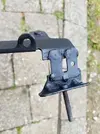
And:
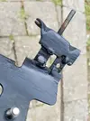
I wish I had some more suitable offcuts of steel to do this sort of thing with! I junked a load recently in order to make some room in my garage...
Also - no jibes about my welding! It's probably the best I've done in a while (that's saying something), but I am not the world's best welder by any stretch of the imagination
Go on - rib me all you like...
And it's not supposed to be exactly straight. I did it that way so one hose could be a tiny bit lower than the other - you'll see why in the next photo!
Anyway, end result:
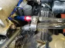
I'm not worried that the nearer hose is at such an angle. I think it'll be fine - don't forget it's a long way from any joints.
Cut and shut:

And:

I wish I had some more suitable offcuts of steel to do this sort of thing with! I junked a load recently in order to make some room in my garage...
Also - no jibes about my welding! It's probably the best I've done in a while (that's saying something), but I am not the world's best welder by any stretch of the imagination
Go on - rib me all you like...
And it's not supposed to be exactly straight. I did it that way so one hose could be a tiny bit lower than the other - you'll see why in the next photo!
Anyway, end result:

I'm not worried that the nearer hose is at such an angle. I think it'll be fine - don't forget it's a long way from any joints.
DaveL485
Staff member
As if we would say a word. I would recommend you buy a welding mask though instead of doing it with your eyes closedAlso - no jibes about my welding!
r5gordini
Well-Known Member
Very funny! I just need more practice. And gas. I ran out of gas so switched to gassless, flux cored wire. It's never as goodAs if we would say a word. I would recommend you buy a welding mask though instead of doing it with your eyes closed
I'm also a bit scared by welding... I really want to be good at it!
Anyway, major, major setback. I was finishing things off yesterday, so booked an MOT for Thursday. Then connected up the rear lights. Something strange happened - the tail lights and indicators were on permanently.
Ah - earth problem I thought! So, I moved the only suspect earth I had - I couldn't remember where it was originally. I should have turned everything off, but I didn't. My belief was that the earth was just for the rear lights.
So, I moved my socket down onto the nut that needed undoing. As I did so, there was a big spark and everything reset! Oh noo....
I moved the earth over then looked at how things stood.
Not good. When I turn on the ignition, the cooling fan starts. Not supposed to!
The ECU does energise the fuel pump but only when the secondary connector that powers the AC relay and the various solenoids. The standard connector doesn't work at all.
I think I've blown something in the ECU! Something to do with the ground circuit. I've had a good look at the ECU PCB and nothing looks burnt but I ran out of time to do anything more yesterday. I think I need to shelve the project for a bit but it's occupying my mind and I'm never happy when I have an unresolved issue.
@DaveL485 - you know how I feel
In addition, the blower fan no longer works at all. This is similar to the issue I had before, but now it seems to be permanently broken. I do now have some more info via the RAOC as to where to look to solve this - apparently there's a PWM fan controller where the transistors on that can fail. Easy fix.
Darn, stupid me.
I think that there was some kind of power surge when the ground point was made, or 12v was injected somewhere it shouldn't have been.
More when I've done a bit more troubleshooting.
DaveL485
Staff member
I do, that heart sinking moment!@DaveL485 - you know how I feel
The earths on my ECU run through the middle of the ECU board so it was hard to see a problem, yours may be the same? I guess you cant really swap-in swap-out a known good unit though because it's so customised
What did your socket touch to short the circuit? It must have touched a live and an earth at the same time. Where was the live point?
r5gordini
Well-Known Member
Thanks Dave!
I managed to spend a few minutes on it during my lunch break today. The good news is that I don't think I fried the MS! I noticed the main fuse to it had blown, so I replaced that but blew it again a few times.
If I disconnect the earth that caused the problem, the fuse doesn't blow and the engine runs! Phew... However, a small problem is that the fuel pump doesn't prime every time. I can't be sure if it always did before this incident, but I'm wondering if it only does if it hasn't been run recently. I don't know.
I think it could be something to do with the aux water pump. With the earth disconnected, the pump runs, albeit very slowly. Massive spark if I put the earth back on with the ignition off, and the pump runs fast again. However, with the pump in circuit, the MS stays live even when the ignition is off!
Interestingly, the pump seems to be earthing itself through the ECU or the wideband O2 controller without the body earth fitted.
I think I may have a couple of problems - a resistance between the earths, leading to the high current taking the path of least resistance - i.e. through the ECU, and a strange current path between the aux water pump and the ECU.
Andrew
DaveL485
Staff member
I think you might be right.I think I may have a couple of problems
I'd start by disconnecting everything I could, then reconnecting one at a time until a problem becomes apparent. Then try and fix it. Repeat until everything works.
See you next year
Similar threads
- Replies
- 4
- Views
- 541
- Replies
- 334
- Views
- 9K

