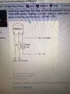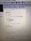
This diagram mate ..........
When I first saw this diagram instantly I screamed NO! and my stomach churned!
I then read the thread!
What is being done here goes against all electronic practices! You are playing with luck and there is a chance this won't work.
The 2N5551 is a NPN type transistor with a max Collector to Emitter voltage rating of 160 volts.
The transistor (as it is often used) acts as a switch and when turned on will allow current to flow through the coil. The current will build up and then remain stable dependant on the impedance of the coil. All good so far!
The moment the transistor turns off all hell lets loose. With the coil (an inductor) cannot change the current through it instantaneously. In such a circuit the voltage at the top end of the coil i.e. connected to the collector will rise extremely high (potentially thousands of volts). With a collector to emitter working voltage of just 160 volts the transistor will fail (maybe)
So why the maybe? if the impedance (a combination of inductance and resistance) of the tacho is sufficiently low it will dampen this voltage spike to under 160volts. Potentially it may also be too high for the tacho input and could also damage that.
I like the idea of using a relay as a cheap inductor (coil) but often relays have a built in diode to stop this voltage spike referenced above. In fact the part of the circuit that screemed at me was the lack of a back emf suppressing diode!
All I will say now is just be careful as there are two components that could be at risk i.e. the 2N5551 transistor (cheap) or more expensively the tacho circuit (although in this configuration it would be designed for a high voltage spike)
When selecting a relay pick a smaller one rather than a big heavy duty which will have a much higher inductance (and a much increased back emf).
I'm sure there are a few other electronics kids out there who have cringed at this


