There is more to life with TurboRenault.co.uk

Register a free account today to become a member! Once signed in, you'll be able to participate on this site by adding your own topics and posts, as well as connect with other members through your own private inbox!

Alpine A610 Turbo - Megasquirt Conversion

Exciting update time!
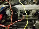
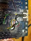
I started wiring up the ECU.
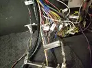
lh3_googleusercontent_com_58a0D0qwNb9yRg6myPYwe_ojFaxfD9OJafzc8881cec8b95d0838c282e9aa1059c4c6.webp

Taking it slowly, I wired in:
  1. Power from ECU relay
  2. Ground (x4!)
  3. TPS
  4. Coolant temperature
  5. Air temperature
And plugged it in...
20170226_212100.webp
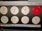
Yaaay! I can read the sensors... Except - the coolant temperature is very low?
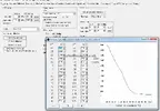
It turns out that there are internal bias resistors for the sensors, so I had to play with the calibration settings a bit to get this:
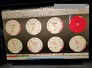
20170226_214958.webp

I may play a bit more, but at least it's now working! I tweaked the settings so that the air intake temp and coolant temp are equal and they have tracked pretty well so far, but only over a few degrees as I struggle to heat my garage over 12 C and it's not dropping very much overnight.
TPS is also showing nicely 0-100%.
I then wired in the TDC sensor and connected up the main battery wire and checked the tooth pattern:
20170227_113319.webp
To my untrained eye that looks pretty good!
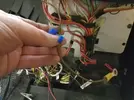
I then wired in the Zeitronix:
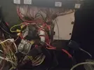
lh3_googleusercontent_com_FBMYsbMmiwayWi4BOlne74wRsHKIhC1yBBt009b359fdd0dd68a1ad7af2557e3c01af.webp
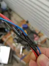
Hmmm... It's all looking a bit messy now! I've added a couple of inline fuse holders and the extra wires are getting in the way. I'll try and tidy it up with some cable ties, but right now it's just a case of getting things working.
The Zeitronix unit seems to be working - it's sending data but I can't test properly until I have the engine running.
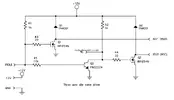
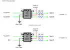
Next I need to wire up the fuel pump relay from the ECU (lack of proper/safe fuel pump control from the old ECU is one of the main reasons for the switch to Megasquirt) and then the coils and injectors. I'm still going to need to construct a circuit to control the logic-level coils. I have ordered the TC4427 from RS. They should arrive today.

Screenshot at Feb 28 09-28-04.webp
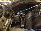
I have started wiring in the relay for the coils and injectors. The high current feed from the battery has a connection point inside the rear o/s of the engine bay and connects to the starter and alternator from there. I'll take a feed from it, fused, to the relay, which will be placed close to the coils and will be triggered from the fuel pump relay. This is my solution for providing high current for the coils and injectors in one!
 
I have also removed the earth strap of doom!
This was added by a previous owner in order to bridge the fuel pump relay so the fuel pump ran all the time the ignition was on. This was required because the OE ECU kept randomly cutting the fuel pump with the inevitable result. Lots of theories abound on the forums about why this might be but no-one has successfully identified the root cause. I suspect faulty injectors leaking too much fuel, making the ECU read rich and shutting down the fuel pump to save the catalytic converter, but what do I know? Anyway, its use was controversial and in my opinion positively dangerous. What would happen if a fuel line ruptured or the car was involved in an accident?
Be gone, you! And take your scotchlok nastiness with you!
lh3_googleusercontent_com_OqFcVDuqUI9aIaFnMy9vY8AAfUDr12UUqvMX8390a5c3949d013fb5c0083bdf98fc90.webp
 
Oh and my exhaust downpipe is away having a new bung being welded in for the wideband O2 sensor - far enough away from the turbo so as not to destroy the sensor.
I've had to buy some extra heat shielding for the O2 sensor wiring because I'm sure it gets mighty hot there due to fact that the left-hand exhaust manifold is right above where the downpipe goes. The O2 sensor wiring is already heat shielded but I want to be doubly sure.
 
The Zeitronix unit seems to be working - it's sending data but I can't test properly until I have the engine running.
Shove the lambda sensor up the exhaust pipe of another car thats running. The harness should be long enough.

I struggle to heat my garage over 12 C
How are you mapping the sensors? I use a thermometer and a pan of hot water, bridge a multimeter over the sensor and read the resistances at x temperatures, key them into the ecu table and voila.
Different sensors have different resistances so you need to be able to map the resistance to temp.
As you can see it's not a linear calibration like a TPS.

01.webp
 
Thanks Dave - interesting stuff! For such an unhelpful manual, the Renault workshop manual does give sensor resistances and these are what I plugged into the Megasquirt, but it only has three values you can enter (which is what the manual gives)!
I've managed to make quite a bit of progress...
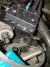
Installed a relay in the engine compartment for the power for the injectors, coils and idle air control valve. Hanging in space for now but I have a proper mounting arranged for it:

lh3_googleusercontent_com_2r0u3d5PNKtHtiXQhyX61kJOj9YN7qDWetIA436f705326cdda95fffd6c3dc5aa7dc8.webp
As with much of the wiring, I will tidy it up later. Promise! The relay is triggered from the fuel pump relay, so the coils and injectors are only live when the fuel pump is live. I added a fuse to the fuel pump wire so that I could trigger the relay without actually running the fuel pump by unplugging the fuse!
Wired up one injector just to test:
lh3_googleusercontent_com_D1XJXX99QOaqAjTLwEkm1p25gxn7vYaUwSSq7acaacc3e3c36ad719dba1376292bf00.webp
Eventually managed to figure out how to enable test mode on the Megasquirt - turn it on in TunerStudio then power cycle the MS then go back into test mode :-O
Wired up 6 x LS1 coil plugs. That took me hours! 24 connections in total. I added a 10uF capacitor inline in the power feed and a 100pF capacitor to the signal wires. The capacitors are supposed to help with noise suppression:
lh3_googleusercontent_com_laPlHGGbszZADfoRxLDtFSBSaFm_xdYLq3ly7a36ad2353d4f5ffb50eceebfaba0b79.webp
Eventually I got a kind of production line running - cut, strip the wires, solder the connectors, fit the wires into the connectors, add the capacitors, heatshrink, done!

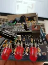
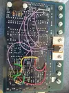
I have also started modifying the Megasquirt - since mine was second hand, someone else had modified it - adding their own circuits. I had to work out what they'd done - eventually I ascertained that an additional coil driver (for 4 cyl wasted spark), a tacho driver and a fan trigger transistor had been added:
lh3_googleusercontent_com_QVHwsJ5itMlw179x4hKLSKSkRgHfzEF83SFWddb6d3dd46f943c87ae158551f37c6fa.webp
lh3_googleusercontent_com_TKGcNFParKato0Hso45drbwKVes5g_gqctkb6355e7bae015405583a802b44c23fb1b.webp
I needed more space in the prototyping area for my circuits but wanted to keep the fan trigger to run a solenoid and the tach driver, so I reconfigured things somewhat - I removed the additional coil driver and moved the fan trigger transistor to its position on the underside of the board:
lh3_googleusercontent_com_n7VcwxAerv2Gea4S72MJcYI0DCizs8xQMjVrfd3489b9eca20fa18d40fec501127081.webp

I also tidied things up a bit and generally made space on the prototyping area.
 
The transistors either side of the fan driver are for the IAC valve - I'm using the Renault original (Bosch) 3-wire idle valve that takes a constant +12v and is either held open or closed by earthing either side of it. I will build this circuit:
Screenshot at Mar 07 17-47-43.webp
I also built logic level driver circuits as per the circuit earlier on this page. 3 outputs - spark A, B and C, and connected them to spare pins in the MS - I removed the original ignition (high power) output and used this as spark A, then IAC1A and IAC1B were used for spark B and C respectively.
Phew!
Then I added a fuse box bus bar type thing - I thought it would be a useful thing for power distribution for the coils and injectors and IAC. I soldered and heatshrunk the connections to it rather than use spades that could come off:
lh3_googleusercontent_com_pUzUJnAsDJoF0Ipmzh9w2J4b1P6GDy8qXlnac6c035a3ddbf0fc73cca5eb76ab720dd.webp

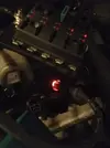
Then I wired the coils (well half of them anyway) up, went into test mode again and was greeted with this:
lh3_googleusercontent_com_YegNxVFLJ4IPp188__Hdyr3_RAdCZAHKJrJc0be6930c7e4bb9d6e7d0d162a1606244.webp
A spark! Wooooohoooooo!
So now I have spark and injector circuits working. Still need to wire up all 6 injectors and the remaining three coils.
 
Bbbbuuuuttttt.... I made a mistake. For some reason (and I more than anyone should know this given my experience with my Gordini Turbo) I thought I didn't need a cam sensor to do wasted spark with the OEM flywheel. Mistake (at least I believe it is)!
So... I now need to build a cam sensor. I'll be using a hall-effect sensor with 0-5v switching. I hope that will be fairly immune to noise.
Luckily I added some spare wires into the loom when I built it - I actually have two choices as to which wire I should use:
  1. The wire that runs with the injector feeds - I twisted it with them;
  2. Or.... the wire that runs with the other sensors
My feeling is no.2 is probably going to be better as it'll be more immune to noise but 1. is easier as I haven't finished that part of the loom. In order to use No.2 I have to undo some of my very carefully done heatshrink and stuff. I'll have to use insulating tape in its place, which will never be as nice ;-(
In other news, I am really glad I fitted a spare wire in with the coil triggers - I thought the coils only needed power, ground and signal, but they don't! They need power, ground, signal and signal ground. I added a black wire with the three trigger wires. Good thinking!

Other quick notes (to get them out of my head so I don't have to remember them all!):
  1. I got the downpipe back from the welders, complete with the new O2 sensor bung
  2. I need to replace the evaporative fuel canister solenoid - it's open circuit so will never work. I think I've sourced a new one but it has to come from afar...
  3. I need to time the engine. No factory marks, so I need to time to No.1 TDC
  4. I need to replace some fuel hose and vacuum and boost sensing and MAP sensor hoses
  5. I need to add spare ports and another connector on the Megasquirt for the IAC, the MAP sensor and the Evap solenoid and boost solenoid
  6. I need to sort out a problem with the fuel inlet into the fuel rail - it's going to be under enormous strain when I bolt it down, so I need to make up some kind of spacer thingy or something
  7. I need to work out what combination of HT leads will get me started - I bought a set of Laguna V6 leads the other day. Fit nicely but not sure if they route well
  8. I need to work out the firing order and which coils to group together for wasted spark
There's still lots to do to get it running but I am excited at the progress. It finally feels that I am getting close.
Andrew
 
Oh argh... definitely going to need the camshaft sensor. Oh well! Only one of the spark outputs fires during cranking.
I'll be building my own. Wish me luck! I hope to enclose it in an original distributor cap. Another argh is that one of my so carefully crafted coil leads is faulty. Not sure which connection or connections but the coil drops out if I wiggle the wire. I'm thinking of making up a spare lead anyway in case one fails and then I can bodge it at the Roadside to get home.
Another argh is that I tried one final test but the power to the ECU was dead. I have a flaky earth connection just while I am building things and it keeps dropping out. At least I hope that's the problem!
 
I'm using the Renault original (Bosch) 3-wire idle valve that takes a constant +12v and is either held open or closed by earthing either side of it.
Much much easier to set up and use a stepper type, they're under £50 and run PWM, only take up one Aux output instead of two. I converted the one i'm doing.

I thought I didn't need a cam sensor to do wasted spark with the OEM flywheel.
You will because of the amount of reset points, the ECU wont know which reset is the TDC one. Same issue for the 4cyl, to use the OE flywheel you need to keep the distributor. Why not just go for a 36-1 trigger wheel?

Or.... the wire that runs with the other sensors
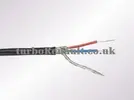
Crank sensor MUST be a shielded/screened cable. Don't just run [a wire] with other wires.
2core-screened.webp
 
Thanks Dave, as always!

I know, I know... after my issues with my Gordini I _should_ have known about the multiple reset points. I just wanted to use the OE crank sensor, although it's not known for its reliability...

Much much easier to set up and use a stepper type, they're under £50 and run PWM, only take up one Aux output instead of two. I converted the one i'm doing.

OK - I'll research it.

Yes - crank sensor is shielded. I don't think the cam sensor needs to be as it's hall effect and will be a 5v square wave (although it might have been better to do so).
I'm learning... Made some mistakes along the way, would do a few things differently next time but I'm enjoying the journey.

Andrew
 
All right - you win! I ordered a universal 36-1 trigger wheel and a crank sensor and a bracket I hope to be able to bodge to fit. I do have a used one already but for reliability I have chosen a new one. Means I have a spare!

I sorted out the dodgy earth last night - meant undoing part of the loom that goes round the left-hand side of the engine bay and feeding through some new wire but I now know I have got a good earth. I was using the OE ECU mounting as an earth as I thought it was earthed but obviously not properly. I was getting cutouts of the ECU during cranking and intermittent loss of power at other times. One of the hazards of a fibreglass car is it's difficult to know which bits are earthed!

The Megasquirt documentation says earth directly to the engine block but I wasn't doing that. I'm now (sort of) doing that!
I worked on the car until midnight last night. It's occupying my thoughts at the moment and I won't be able to rest until it's running...
I hope I'll get some more time on it tonight and over the weekend. Next job is to fix the one coil wiring plug that's not working properly - need to identify the cause first. Dodgy connection in the plug? A fault with the capacitors that I added?
I've got a couple of spare plugs so I might just make up a new lead for that coil. Benefits of buying coils that were originally for a V8 but now fitting them to a V6!
Andrew
 
Great read! Looks like this saga will be running for months yet! have you decided which September you will have it running/driving by???!!!! Love it when people try something a little bit more extreme and get it to work, then refine it into something to be proud of:bp:
 
Back
Top