There is more to life with TurboRenault.co.uk

Register a free account today to become a member! Once signed in, you'll be able to participate on this site by adding your own topics and posts, as well as connect with other members through your own private inbox!

Alpine A610 Turbo - Megasquirt Conversion

OK - a quick update...

I totally bodged up removing the inlet manifold www.renaultalpine.co.uk_images_smilies_icon_butt.gif - requiring me to take the turbo to someone to remove a couple of snapped studs - one from the turbine exhaust housing and another from the big bracket that holds everything together... I am pretty upset with myself as if I'd only read the manual it would have saved me a lot of bother. Oh well. Live and learn!

I have decided on some injectors:

http://www.ebay.co.uk/itm/221756514759? ... EBIDX%3AIT

They are Siemens Deka 660cc ones. @Lee21T came round at the weekend and was discussing that he'd used them on his R21 Turbo and they work just great! I was concerned about low duty cycles at idle and part throttle openings but apparently they are designed to be very linear and controllable. Now need to save some pennies to buy them, because I just ordered this wideband O2 controller and sensor:

Zeitronix Zt-3 controller and sensor - EFI-Parts.co.uk: Connectors, Sensors, Trigger wheels, Wideband, Adaptronic, Zeitronix, AEM

I've decided to mount it towards the end of the down pipe - it's just far enough away from the turbo there. I'll need some heat insulation for the wiring because it's right in amongst the exhaust manifold and the down pipe. Bonus is that the place that's sorting my snapped studs can also weld in O2 sensor bungs! They are 5 mins down the road. I was going to go to somewhere 45 mins away, so that's useful.

I had a day off work yesterday to make some significant progress. I have pretty much laid out all the wiring for all the sensors, etc. but want to redo the knock sensor and TDC sensor wiring as the cable I bought from eBay is a bit large in diameter and I'm not very happy with it, so I ordered some screened cable from EFI parts.

In order to minimise RFI from the injector and ignition wires I have totally re-organised the way the wiring works. My basic rule is:

Anything that goes "to" the engine or that controls anything on the engine goes round the left-hand side of the bay;

Anything that receives anything from the engine goes round the right-hand side of the bay;

Except for the boost control and evap control solenoid, which have to be on the right hand side; and the wideband O2 sensor, which has to be on the left-hand side (probably).

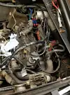
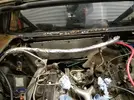
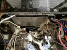
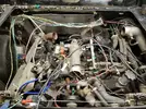
I twisted and grouped all wires and have ended up with an engine bay that looks like this:

lh3_googleusercontent_com_hioGd4Ntw0sucDHUfDEQcEFjweSq9XSlNDma6fb068abc0d78528cf0f8e06d3c38e80.webp

I haven't screened the sensor wires (except TDC and knock sensors) but they are already done better than OE so I hope that will be good enough.

Andrew
 
Custard:

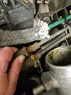
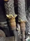
Looking good that must have been a bich removing the turbo with it in the car. Looking at your fuel lines you need to check them, pull back the heat matting and check the braiding into the swage if it's all fallen apart you need to change them, as the new wireing will not stand a petrol fire.
 
hanks Custard!

They look OK at the end closest to the bulkhead but I'd need to cut the clips off the ends of the fuel lines at the other end to inspect properly.

lh3_googleusercontent_com_KC_5Rv5NvmgV0_wBx_LsYeKvwZOi_seOHjor8d121dc81f258a82f5cb932a51eb9551.webp

and:

lh3_googleusercontent_com_BMOiEuUMJrFGJcaIUkc01t6NjApINkwxttdkb8dd6369c2462b9cbf1bcf37f479232e.webp

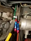
Do you know how I would replace the swaged ends and the flexible fuel pipes without removing the hard fuel lines?

Do you know what the green metal pipe is? The one most inboard of the three metal pipes - fuel in/fuel out and ???

Thanks,

Andrew
 
Think I've answered my own question?

AN-xxx hardline adapter?

http://www.ebay.co.uk/itm/AN-6-AN6-STRA ... 8shKgmKUPQ

Don't know which AN to go for - I think I'd feel happier if I replaced these lines though. I am already going to replace the fuel hoses to the rails.

I plan to replace the fuel pipes underneath the car too but maybe not this time...

I used a load of AN fittings when I did my GT Turbo power steering conversion a couple of years ago. Very handy - lots of fun making up custom lines!

Andrew
 
Hehehe....

OK, OK - I will renew them. I'm not intending to take the engine out! At least not for now.

I presume the challenge of changing all the fuel hoses is the accessibility next to the gearbox with the air-con pipes in the way?

Should I be worried that the main feed to the fuel pump doesn't seem to have any kind of hose clamp on it?

The fuel feed is the lower of the two in this photo:

lh3_googleusercontent_com_Xye_ZXr1_UdJzmNE1WP_lVkQqk3zq4z4MQOYf6dcc056f56be98502895f338db23b68.webp

Why do I get shipwright's disease every time I get embroiled in a project like this? My thoughts go something like:

"While I'm in here, I've got this part off, so I might as well renew/improve/upgrade it"...

I have bought some fittings for the fuel rail and the fuel hard lines. Don't know if I've got the right ones so I've just ordered one of each and will get more if necessary. I'll use AN-6 teflon hose and will get some heat insulation sleeving to cover it too...

Andrew
 
I would change the main lines they look like there time has come to an end. Did you check your knock snesors, shine a light in there mine where both cracked as you have the turbo of its not to bad a job. Like mine the list goes on on on on on on. www.renaultalpine.co.uk_images_smilies_icon_crazy.gif
 
I checked the knock sensors. Both are intact so I think I will leave them alone. The knock sensor interface I bought has a LED that lights when knock is detected so I will use that when the car is running. I may even be able to use it to test them once wired in by tapping the sensors to trigger them.

Exciting stuff! Wideband O2 controller and sensors arrived. I bought the Zeitronix ZT3 from the legendary Scoff...

More wiring done. Starting to tidy up and wrap the loom then will start putting connectors on the end. I made a couple of decisions, for example will use relay(s) in the engine compartment to switch the high current feed for the coils and the injectors directly from the main power connector rather than feed high current from the fuel pump relay. Saves space in the loom!

I am also going to use a relay to switch the engine compartment fans on to avoid using a high current feed to the temperature switch.

I am sure I have forgotten a wire or two. Becomes harder to feed in once the loom is wrapped! I'm using the braided plastic sleeving stuff...

Andrew
 
file.webp


I also ordered connectors for the fuel rail and supply. AN-6 to 8mm hard line (compression) and AN-6 to M14x1.5 inverted flare. The latter is important as it connects directly to the fuel pressure regulator (I'll do away with the small bit of hard line that goes from the fuel supply line to the regulator) and to the outlet from the right hand fuel rail. I will be using teflon stainless braided pipe. I worked with it before when I did my power steering conversion on my GT Turbo. It is very satisfying to work with as with little effort you can produce professional looking braided hoses.
 
And another update! Fuel injectors ordered www.renaultalpine.co.uk_images_smilies_icon_e_wink.gif

630cc Siemens Deka high impedance... According to the blurb:

These injectors flow 60 lbs/hr at 43.5 PSI ( 3 BAR ) and up to 85 lbs/hr at 87 PSI! In addition, these units are high-impedance. Despite the high flow rate, they are linear and controllable at low pulse widths and have been used in ULEV applications! This allows you to use a larger injector than normally possible without hurting idle and low speed driveability. Adding to the flexibility of application, these units are high-impedance; making them compatible with most ECUs, while delivering the most flow available in a High-Impedance injector.

These injectors are able to function at high fuel pressures and don’t exhibit the high fuel pressure handling problems found with many other high flow high-impedance injectors. This makes these injectors very well suited to turbocharged and supercharged applications that see high fuel system pressures.

Engine performance and running quality are enhanced through the optimized spray pattern. Unlike competitors “pencil stream” high flow injectors; these High Flow injectors utilize a multi-orifice tip providing a true 30 degree spray pattern for improved mixture preparation. This results in lower BSFC and better idle quality than many injectors with less flow.


Looking forward to fitting them!

I have also decided how I am going to control the fast idle air valve... After lots of research, I will build this circuit:

3-wire PWM Idle Valve and Coil Driver Board

It allows direct control of the original 3-wire Bosch IAC that's fitted to the A610. Fun, fun fun! I don't have a PCB for it - I may use the prototyping area on the Megasquirt or I may just build it into a small case. I already have three other "boxes" to install!

* Megasquirt
* Zeitronix wideband O2 controller
* Knock sensor controller

... and now this.

I am also progressing with my thinking for the installation of the coils. Some may not like what I am considering, but it's only unconventional from the point of view of the materials I am thinking of using. Lightweight, strong and flexible.... (hint: not fibreglass)...

And so, back to my cold garage I go, for more wiring!

Andrew
 
Sorry it's been so long since an update. I'd love to hear others' comments!

Good News! My turbo is back from the welder/fabricator - I broke a couple of studs through my own stupidity, so those have been extracted. One might need to be helicoiled in the turbine housing but I'm going to run a tap down the threads to check them - they might be ok. The stud needed to be drilled out...

I have started with the fuel hose replacement. As I measured the hard-lines, they were 8.3mm. Hard-line adapters are 8mm. I don't know whether the .3mm was due to rust, paint or whatever, but I couldn't easily get the compression fittings onto the steel pipes. By careful filing down to bare metal all round, I was eventually able to fit them:

lh3_googleusercontent_com_dbdiZSKnWB8pCpte44O_DEGRbXROc9wc5J200262d891fd3d09ae6f3dbe4868a72b19.webp

Unfortunately I slightly damaged one fitting - just due to refitting it several times - some of the anodising has come off. Doesn't affect its operation. I had to buy some spare compression olives too as my first attempts at fitting the supplied ones didn't go too well - they got stuck at the very end of the pipes and needed cutting off.

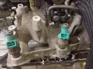
The new injectors arrived! Old:

lh3_googleusercontent_com_qt_IVd5AHJC5uzHjD3KflMVNLQ1g_Fb0d_pC7815b0fa9d79457bbeb7011686fbc140.webp

New:

lh3_googleusercontent_com_siLtURDZgbKFwmC4GzduAZJ3D7TFp_i4_WHoeeb7eff22e2c4eafa989aae0e7d10740.webp

You can just see the multi-hole pattern in this photo:

lh3_googleusercontent_com_nqlc0VCt9xAyeLgMlh50U64n1ltc_R4tGRame212ec8b5d7a62979698ab79e54254fa.webp

More later...
 
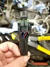
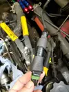
The wiring loom around the right-hand side of the engine bay is essentially finished. TDC sensor wired up - I had to modify the plug as I couldn't buy exactly the correct one. They all had the cut-outs in the wrong places, so I cut new ones using a Dremel. It makes the plastic locating tubes more flimsy, but when it's plugged in it doesn't matter. I was very worried about the ends of the wire to the plug being vulnerable to vibration, etc., so I enclosed the end of the plug in heatshrink and a small piece of convoluted tubing so that the point of stress was transferred away from the small bit of exposed wire:

lh3_googleusercontent_com_4MzDfUuk5ane3SrE18PQJH5d3o0VpmhjYM5def68c92147997a0bc91b1820f18bb8d8.webp

lh3_googleusercontent_com_odJ80dEcF2bhEEx_mr2pk7usI48OVirkQ_cP4189cae802dc47070e08fcad757fe40f.webp

And my DIY cutouts (not that easy to see):

lh3_googleusercontent_com_aKHFbiUZSJscP2mvY50Pzjn_sN0PxfM9MWYjda4f6e812804caaf3216523ab1564cc0.webp

Right-hand side loom before convoluted tubing:

lh3_googleusercontent_com_wGaQXMabUZyNeUQ1Hh_QxwQSRgppSse3X5DD84ae86cbb9347fe4a7bd48172e7a9a65.webp

I decided to protect the left-hand side loom with fibreglass heat shielding, where it runs above the turbo. Might be overkill, but the original wires were a little bit cooked. They were surprisingly OK but I decided discretion was the better part of valour, so this is what I ended up with, which I think is quite cool:

lh3_googleusercontent_com_uoqZcgARZ2KoudFWkcfmXcEm0EoNbAjrGTc2a0111cd8ddd4e03e691deb56c0925792.webp

And:

lh3_googleusercontent_com_M3O_ka8NwEjY6vrx__LrVAbhusCWhkxUrLzse294285d27821922f0b4dee76b1fd8f6.webp

It's split heat trunking - has velcro to hold it together and makes a nice, neat job. Unfortunately I did get a couple of fibreglass strands caught in my fingers. Gloves next time!

I've also started connecting the new loom to the OE loom inside the car - starting with the temperature sender wires.

I'm still not sure how to mount the coils - worried about long HT leads from the left-hand rear shelf across the engine. But making up a bracket to hold them all on top of the rocker cover on the left-hand bank of the engine isn't really practical either.

Ho hum...

Oh by the way, I have decided to do without the cam sensor for now. Don't know if that's a mistake or not, but we shall see. I'm just going to batch fire the injectors. Consensus of opinion is that it makes very little difference. Maybe get slight improvements at idle and throttle transition, but Megasquirt has lots of interesting things that one can tune to enhance these bits. I'm learning lots!

One of the more interesting things is X-Tau, which is for transient enrichment. My understanding is that lots of fuel puddles on the walls of the inlet manifold and inlet into the cylinder head. You need to inject more fuel into the cylinder to compensate for that, otherwise the mixture will go lean, until the point at which all the fuel is pulled off the walls into the cylinder (eventually).

I'm sure I'm going to have fun experimenting with it!

MegaSquirt-II X-Tau

Andrew
 
Where do we start, Andrew? Interesting, interesting. If i'd have known i'd have had a chat with you about why you should have gone with an encased ECU (as you know my preference is an Adaptronic) but this will be MUCH more entertainment for us!

It was my birthday today so I was allowed to do whatever I wanted!
:D LOL Do you have a flat spot on your noggin where her thumb sits?


They are Siemens Deka 660cc ones.
I was going to suggest the VXR blues as they are pretty cheap brand new but the Siemens are a good choice, got those on the install i'm doing at the minute.

Zeitronix
Good choice, I use one of these too. Good kit for the money. It outputs serial to the gauge via RJ11 and you can split that signal to interface direct with the ECU and run the gauge in tandem.

AN-6 teflon hose
Remember you can't jubilee clip Teflon line (but looking further down I don't think you intend to)

worried about long HT leads from the left-hand rear shelf across the engine.
HT's will feck up anything close by. I had some loom wiring near the main loom temporarily while I was still mocking up and the feedback along the lines kept corrupting the map file in the ECU. Just make sure the coils and leads don't get too close to any of the engine harness.

transient enrichment
Transient isn't anything to do with pooling. On an engine tuned with a MAP sensor the ECU has to do filtering on the MAP sensor signal to get a smooth enough signal to use for tuning purposes. This filtering slows down the response of the sensor so when you snap open the throttle, the MAP reading that the ECU sees doesn’t change straight away but the demand of the engine does change straight away, because the pressure wave travelling through the throttle to the intake ports moves at the speed of sound meaning the engine needs the extra fuel immediately. When you snap open the throttle from idle the manifold pressure will go from 30kpa(ish) to 100 kPa in a matter of milliseconds, but the MAP sensor reading will slowly go up to 100 kPa over a period of a few hundreds of milliseconds so you need to use MAP prediction. When the ECU sees a quick throttle movement, it looks at the predicted MAP table instead of the MAP sensor, for a fixed duration. Once that duration is up, it goes back to looking at the value from the MAP sensor. In the case of an Adaptronic during this time the ECU actually picks whichever is greater out of the two (the MAP sensor and the predicted MAP value) so that if you’re on boost and nail the throttle the last few percent, the ECU won’t reduce the amount of fuel.

Note: The above is semi plagiarised from Adaptronic :)
 
Thanks Dave, as always!
Your posts are always witty and informative!
If i'd have known i'd have had a chat with you about why you should have gone with an encased ECU (as you know my preference is an Adaptronic) but this will be MUCH more entertainment for us!
You mean it'll be funny when it doesn't work? I just like the Megasquirt philosophy. Yes, it's probably going to be harder and take more time, but it will teach me a lot in the process and I can customise the ECU to my heart's content! It's also cheaper - I had a Megasquirt that I bought from a friend for £100...
I was going to suggest the VXR blues as they are pretty cheap brand new but the Siemens are a good choice, got those on the install i'm doing at the minute.
Yep - they were on my shortlist. I really liked the sound of the Siemens ones. Should be good. They're installed now:

lh3_googleusercontent_com_aHOYYVowU7KRTbUsFD3rRpLnBg75JjwMJEub3608d9c74493edf55cbc011beaeb2cc5.webp

Notice the AN-6 adapter screwed to the right-hand fuel rail...

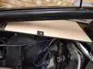
Now on to the issue of the HT leads. First of all, to mount the coils, now for some highly advanced materials science. I mean bodgery... I decided to use some 9mm plywood to strengthen the left-hand shelf for mounting the LS-1 coils. I'm going for two towers of three coils - space constraints dictated that due to the proximity of the engine bay cooling fan. Once the ply is in place, no-one will ever know (except for you lot) as it'll be covered in carpet.
Don't :cl: me!

I used CAD (Cardboard Aided Design) to make a template:
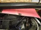
lh3_googleusercontent_com_4cWYeF09K6WGBQJIDegzbOFe_YNCjeNhqPa696fede845f02a698268500464a848aba.webp

And then cut it out in ply:
lh3_googleusercontent_com_pXC_7XIrfDG0VWoExY82FljmxiOjriueHh943798de08fc4615e143a5d3cc2fa123ee.webp

I also reason that the car is fibreglass anyway so it's now just got another advanced material in it! I made the ply part to cover the whole shelf as there are a couple of strengthening braces and brackets that I wanted the plywood strengthener to cover.

And then I mocked up the mounting of the coils. I didn't have long-enough bolts, so here are two coils mounted and a third mocked up:
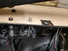
lh3_googleusercontent_com_U2waD_zdfHc99gyTHZIsmsG0qUKiNdQ41mcK5532d85a059883d751854acd6671c3c3.webp

Unfortunately I slightly damaged the plywood when I drilled through it, so I may strengthen those drilled areas with some epoxy. Again, a bodge... I know, I know! I won't make any excuses. It's my car...
I'm using rubnuts to make captive nuts. They are like rivnuts but made of rubber!
The later attempts at drilling through the plywood were better as I put something behind it to stop the drill bit bursting through and breaking the outer layer of plywood.

My perfectionism may get the better of me again and I might end up having a second go at making the plywood shelf, but I think I'll leave it for now as I just want to get the car running!

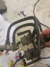
For reference: fuel pipe layout for the fuel pressure regulator and pulse damper. I am renewing the rubber hoses:
lh3_googleusercontent_com_jjr2w7T_yVLKd70Q5N1L56Vd0ApZou1oxEkE4da8a3810812ac80b8f98fe6484b2e29.webp

Note the lego man and instructions in the background! My son has been using my garage for lego building as I work on the car. Father/son time (sort of)! The pressure sensing hoses on the top of the regulator and pulse damper thingy are well past their best so will be renewed too.

The fuel hoses seemed to contain a plastic inner. I was worried that there were no hose clips on them, but, boy were they tight! No way they were coming off in a hurry - I had to cut them off.

Thanks Dave for your advice on enrichment and the HT leads, etc. I will route the HT leads as best I can. I'll need to get some custom ones made up and can use some of the OE routing for them.

Oh and yes, not going to use jubilee clips for the teflon line. I'll be doing that bit properly!
 
Your posts are always witty and informative!
:comeon:

It's also cheaper
But is it? The point i would have made would be 1)the immense time investment has a 'cost' and 2)with the base ECU's often you will spend as much getting it to work as a package ECU. Crude example an E420 has a built in 4-bar MAP sensor you dont need to buy separately. It maps to any sensor, temp and/or pressure so you dont need new ones. And blah-de-blah.

Too late now but food for thought for the next Andrew reading this to make an informed decision lol
 
Back
Top