There is more to life with TurboRenault.co.uk

Register a free account today to become a member! Once signed in, you'll be able to participate on this site by adding your own topics and posts, as well as connect with other members through your own private inbox!

Alpine A610 Turbo - Megasquirt Conversion

As you are probably aware, I started a thread a short while ago discussing the benefits of a standalone ECU on the A610 and which one I should choose.

After a lot of deliberation I have decided to go entirely DIY! I already have a Megasquirt ECU sitting on my bench so I think it would be silly not to at least try it. I will also make my own loom. I enjoy the challenge of a custom build and figuring out all the problems along the way.

I will be keeping the original loom so it can be reinstated at any time. The custom loom I am building can be adapted to any ECU so I was going to leave enough spare wire that I can switch to an Emerald or Adaptronic in future if the Megasquirt doesn't work out.

So... onto the plans:

  • Megasquirt 2 v.3.0 - I will be using the MSExtra firmware for its additional features
  • Custom, home built loom with brand new connectors throughout. I may solder (gasp!) the connections, but they will be strain relieved with heatshrink
  • 50-way military spec multi-connector in place of the original multi-connector in the engine bay. I chose 50-way so I had more than enough spare connections for additional features
  • Braided sheath everywhere it's necessary
  • Use original crank sensor and build a DIY cam sensor for phasing
  • Use original Amal valve for boost control (for now, at least)
  • For ignition, use Chevrolet LS1 coils - one coil per plug, logic voltage triggered (this reduces electrical noise and gives me a lot of freedom for mounting the coils)
  • Semi-sequential injection
  • Wideband O2 sensor (probably)

That's the plan at least! Let's see how it goes www.renaultalpine.co.uk_images_smilies_icon_e_wink.gif

Andrew
 
From Martin F:

Hi Andrew,

Great that you are tackling this well done. It's not rocket science, so should work out well.

Some points I would raise:

1. Loom interconnects, bulkhead connectors - great adds flexibility and ease of maintenance, but reduces reliability significantly, even military conectors, they are one of your highest failure points, I do this sh_it for living, and we are always looking to eliminate them. So I would say, if you can avoid the bulk head connector, simply do... you are not going to be pulling the loom, replacing the engine more than once, max twice in the vehicle's lifetime.. certainly not on a frequent basis. The "connectorisation" if you like, assists faster cheaper install for the manufacturer, it doesn't add technically to the quality, just convenience. Keep it simple if you can, but I do understand allows additional wires to be run in later, but you could make provision for that now with planning.

file.webp
RM1438623505.jpg (14.28 KiB) Viewed 240 times


So I know a thing or two, lets say two, of military connectors, harsh environments, and reliability data...

2. Single bulkhead feedthrou connection will defeat your attempts at signal integrity, screening effectiveness, and signal type isolation that you had with your cable screens to that point in the loom- you have no choice than carry your screen through on a pin... your screen at that point is defeated... not techno ballshot, just plain fact. The only solution as we do, is to use guard rings round sensitive signals, and that takes up a large number of pins on your multiway...

3. Have a look at the automotive -55 +125 deg C Molex to name one, excellent product for power, signal, and wire to wire interconnects... the automotive manufacturers have done more work than anybody on suitable and sufficient product to meet high reliability and lower cost... all cable harness reliability studies with real field significant data are automotive...

4. If I understand right, you are thinking of keeping the OE variable reluctance tdc sensor, and presume trigered off the OE flywheel tooth pattern? All good, just remember, you will then need the cam sensor to identify tdc no.1 for ignition as well. But should be easy, as the cut-outs are already in some versions of the cam sprockets, come in through the front timing case cover.

5. Controlling the Amal valve is one option (I think it's 3 wire from memory, could easily be wrong though), or there are cost effective, and reliable single ended solenoids you could just control from a pwm output.

6. IMHO I wouldn't sweat a bunch over (semi) sequential over batch injection fire necessarily, we're not F1 here, and the 12V PRV isn't the most lean burn engine by far, so not a huge amount to gain in reality, semi is nice to have, but wouldn't add the cam sensor to get that, only really so that you can go coil packs and lose the dizzy.

7. IMO I would go high impedance injectors, and save the need for the higher current peak and hold injector drivers.. yes we could argue the relative merits of this and that, but modern multi-spray injectors.. whack 'em in...

Biggest thing though, as already comes through in your post - enjoy it, it should be a fun project full of discovery. Great go for it, keep us posted as Vince says ww.renaultalpine.co.uk_images_smilies_icon_e_smile.gif

Martin
 
Vince, Martin,

Thank you for your encouragement! I've started amassing the bits - it's unfortunate that I didn't post earlier as I've already gone and bought the multi-way bulkhead connectors! I'll quote against various comments here:

1. Loom interconnects, bulkhead connectors - great adds flexibility and ease of maintenance, but reduces reliability significantly, even military conectors, they are one of your highest failure points, I do this sh_it for living, and we are always looking to eliminate them. So I would say, if you can avoid the bulk head connector, simply do... you are not going to be pulling the loom, replacing the engine more than once, max twice in the vehicle's lifetime.. certainly not on a frequent basis. The "connectorisation" if you like, assists faster cheaper install for the manufacturer, it doesn't add technically to the quality, just convenience. Keep it simple if you can, but I do understand allows additional wires to be run in later, but you could make provision for that now with planning.


Ho hummm... See above! I appreciate what you're saying and you're probably right but I already planned to do it that way and so ordered the various connectors ahead of your post! I actually ordered two of them from different sources (much cheaper on eBay) so I could have an extra shell over the wiring as I couldn't find the shells separately... I think I'll still go with them, as I like the separation aspect. I'll probably run extra wires from the socket through the loom into the cabin, but leave them unconnected in the plug - that leaves me room for future expansion and then I only have to wire in the extras when I need them.

For reference, I bought the following connectors (sorry Martin):

http://www.ebay.co.uk/itm/1Pc-Military- ... SwBahVKJQZ

Y2M-50TK - they appear to be Russian but made in China - I got the original one from TriggerWheels.com but found them for half that price (approx £12.50) on Amazon and Ebay. Can't be bothered with the faff of returning to TriggerWheels!

I ordered a loom wiring kit from Trigger Wheels and some 2 way and 3 way Junior Timer plugs.

Another mistake was to order male and female 3-pin Econoseal connectors from EFI-Parts. I thought they looked compatible with the OE O2 sensor and TPS but they aren't. They are a lot smaller...

So, I now plan to not worry about the O2 sensor as I'll be going wideband, which requires a separate controller anyway. I'll get the proper connectors for that when I decide which wideband controller to get (and I've sold some more stuff to make up the cash!). Regarding the TPS, I will rewire the OE TPS to use the 3-pin Econoseal connector and then I'll have a matching connector for the loom. If I ever do go back to the OE loom, I'll just replace the 3-pin connector on it with an Econoseal one anyway - the wires in my loom have been bodged before, so it would be good to replace them if they're ever needed.

Regarding the OE TDC sensor, I will use screened cable for it and will most likely not join it anywhere until the loom. That saves passing a screened connection through the multi-way. Good idea to keep it separate anyway.
4. If I understand right, you are thinking of keeping the OE variable reluctance tdc sensor, and presume trigered off the OE flywheel tooth pattern? All good, just remember, you will then need the cam sensor to identify tdc no.1 for ignition as well. But should be easy, as the cut-outs are already in some versions of the cam sprockets, come in through the front timing case cover.​


QUESTION: Does anyone know where to get the female connector for the OE TDC sensor? What's the connector called? I'd like to keep the OE connector, but if not, I can get any 2-pin waterproof connector pair and use that instead.

Yes - already planning for a cam sensor. My plan is to use a hall-effect sensor with a magnet on the end of an OE rotor arm, modified to hold the magnet. I've received the sensor and magnets - here's the sensor I plan to use:

http://www.ebay.co.uk/itm/121522431810? ... EBIDX%3AIT

Looks pretty cool, doesn't it? Should be reasonably easy to mount and is nicely encapsulated. My research tells me it should work, given its specs.

5. Controlling the Amal valve is one option (I think it's 3 wire from memory, could easily be wrong though), or there are cost effective, and reliable single ended solenoids you could just control from a pwm output.​


Looks two wire to me - want to control it from a PWM output...

6. IMHO I wouldn't sweat a bunch over (semi) sequential over batch injection fire necessarily, we're not F1 here, and the 12V PRV isn't the most lean burn engine by far, so not a huge amount to gain in reality, semi is nice to have, but wouldn't add the cam sensor to get that, only really so that you can go coil packs and lose the dizzy.


Yep - fair enough. Thanks!

7. IMO I would go high impedance injectors, and save the need for the higher current peak and hold injector drivers.. yes we could argue the relative merits of this and that, but modern multi-spray injectors.. whack 'em in...


Oh... Darn, didn't realise the injectors were low impedance. Was hoping they were high impedance. I don't think my budget can stretch to new injectors right now, although I have no idea how much they cost.

QUESTION: How would I figure what would be good injectors to choose? For now I think I can use PWM to control the low-impedance injectors, or use a current-limiting resistor (although that can cause problems with slow opening, I believe).

Thanks!

Andrew
 
So.. first set of problems overcome and photos to upload!

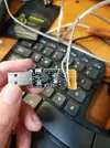
No.1 - establishing communications with the Megasquirt. I used what I had in stock - a USB-Serial adapter:

lh3_googleusercontent_com_F2RVaY6uay3ZTXwEv1Y3Wr8VsHX_Na5O4CkH33e70917bbef4702a45bd844ae305d79.webp

But try as I might, I couldn't get it to work - maybe my bodged, unscreened cable was the problem as I could get a loopback back out of the cable at 9600 baud but not 115200 baud, which is the default for the Megasquirt 2! Don't worry, I'll do better than that when I do the car, I promise!

So I bit the bullet and spent £11.50 on a proper USB->Serial cable from Amazon:

https://www.amazon.co.uk/gp/product/B01 ... UTF8&psc=1

And it worked straight away! Result www.renaultalpine.co.uk_images_smilies_icon_e_wink.gif

I also have a bluetooth adapter, which I plan to fit to the ECU some day, but serial is all I need to get started.

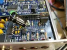
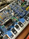
Here are some photos of the inside of the ECU - it's had a few mods, which I have yet to work out what for, but the good news is that I am now able to communicate with the ECU and flash it and tune it appropriately.

lh3_googleusercontent_com_kfitZWY1E7q5VQ_Kz98WoZkQtIEeyCi44qSIda239a9fe8f6ad19a1215316b45c66da.webp

Note the cut diodes... There may be a problem with a couple of the injector drivers, but I hope it's something I can fix, if so. I need to do the troubleshooting first.

lh3_googleusercontent_com_Bu1awJq4cTOx1DjQSHHFzwnFK8XnVvwv_1Xd133d6547731481607823fd5e956e5e5f.webp

Exciting first steps!

Andrew
 
From Martin F:

Great, really pleased you are going for it, and not been put off... One comment, don't take it the wrong way, that isn't a military connector... it is a cheap tat Chinese copy, please don't waste your good work and hours by putting that in the middle of it... go bulkhead connection, but please please use a real part... genuine military connectors are specified to defined standard series, qualified, and then built and proven to maintain that performance, they are expensive... and for good reason... many different families to choose from, with different applications and adaptors, back shells, receptical arrangements, body types etc etc... MIL 38999 series 3 is similar to what you have there, check Farnell... MIL 5015 is another good series...

If you stay with the one you have, my money is on intermittent niggling faults that appear in the damp, and when you drive over speed bumps for example... and you will kick yourself for finding the cheapest thing, and being pleased with finding it cheaper still.. it's cheap for a reason, it's crap... there won't be the receptical / contact sealing, the seal between the contact bung and the body, the inter-facial seal will be missing and no IP rating, the plating on the pins will be microns and will wear very thin or fail with contact vibration in road shock and vibration, I can go on.... Put it in the bin, smile, and get good part and will have a better result ww.renaultalpine.co.uk_images_smilies_icon_e_smile.gif

Smiles,
Martin
 
More from Martin F:

The USB thing is a signal integrity issue... a bit of wire is not just a bit of wire, it is a transmission line, especially with fast clock and data edges, as you have... hence the reason it worked to a degree at a lower baud / clock speed... I think it is fantastic you are learning these things, so keep going, but you will have lots of these niggly things, it is an integration task...

So I would:
screen your tdc and cam sensor signal, and make the wire a twisted pair - segregated in the loom
screen your actuator bleed solenoid, again twisted pair - segregated in the loom
your air and water temp signals are low level analogue interfaces - screen
throttle pot, low current, relatively high impedance, twist and screen if you want a good low noise reference

your injectors are relatively higher current depending impedance, and will be one of your EM noise source currents - segregate with similar, such as air bypass valve

the high pressure pump can be a high noise source through commutation currents, shunt the noise with a suppression cap at the pump

consider well where you get the power feed for the coil packs, and where the trigger signal return is taken

study the MS forum and tech advice on the input power supply integrity and filtering - apply it carefully
check whether your version of the MS board has transient suppression, and also has protection from load dump ie intermittent battery disconnection (bad / loose / corroded battery terminal connection) when the engine is running...
check whether your version of he MS board has reverse polarity protection... we all do it, make silly mistakes, and then...

Cheers,
Martin
 
Thank you Martin and Stephen!

Ok, ok, I'll ditch the military connectors!! I just thought they were fun and replicated the OE setup. In fact I won't use any kind of connector mid way through the loom at all.

I will go completely custom and individual wires.

I'm thinking of using separate bundles but yes, point made about screening and the like. We actually have quite a long run for the loom into the cabin. And lots of mixed high current and signal wires.

Plan for tomorrow is to start to remove the factory loom and inspect how it's done. Then I can decide which bits need to go where and which bits need to be improved. Need to clear a bit more room in my garage so I can work on the back of the car with the garage door shut and also need to declare SORN. Great winter project, no need to pay tax while all this is going on!!

Andrew
 
I was hoping for a day working on the 610 today but a painful shoulder and neck put paid to that!

I have started removing stuff to get access to the loom and was hoping the engine loom was separate from the other electrics but it's not!

I'm not quite sure what to do next so I'll sleep on it and get back onto it next time. Meantime I'll continue removing stuff so I can get access to everything I need. First major job I've tackled on the 610 so I'm learning as I go!

Andrew
 
Update time! It was my birthday today so I was allowed to do whatever I wanted! What better way to spend it than on the A610.

I have managed to remove the entire rear loom (well, the RHS anyway).

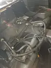
Here it is, all curled up in the back!

lh3_googleusercontent_com_XD15KQQbXJqRwD7fbfgxZHMzjB3oMcijd0Lyd864d47567ecec77a13b206907ee3e6a.webp

There are some things that the loom plugs into, solenoids and sensors, etc., that I haven't yet identified. Dunno what they are! But I am encouraged to have been able to remove the loom.

I do notice that the OE map sensor is a standard GM 2 bar sensor, so I've ordered the standard GM MAP sensor plug.

Now to let my sore fingers recover and think on next steps!

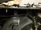
It was a fun job. I spotted a couple of issues along the way, like a squashed air pipe that was trapped in a bracket (not sure exactly what it is for) and the right hand engine bay fan mountings have pulled out of the fibreglass, but these are all issues that can be addressed later on.
Have you got yourself a Jimstim board for he MS to provide the input signals? The OE air temp and water temp sensors should be ok with the MS, as they are NTC. The throttle pot again, you should be able to use, don't forget there is some series resistance on the wiper connection with the OE pot you may need to take some consideration, so not completely ratiometric, bug close enough. I would have to look up what the actual value is, but around kilohm. I think you will need to test and simulate on the bench for the cam sensor timing, and make ure it all happens at the righg time. Have you got an oscilloscope?​


No Jimstim board - thanks for the suggestion - I had seen them before. I'll consider getting one. Yes I have a 'scope. Or two. I've got a thing that plugs into a USB port - it's quite handy. And I have a kit to build a nice portable one. I was going to use it for troubleshooting the ABS on the A610 but this project has taken priority!

Andrew
 
Oh and regarding my comments about not yet identifying the solenoids and sensors - that's my next step. Photos have been taken. Connectors will be identified and traced back into the loom so I can understand how it works.

Andrew
 
One more thing... I may also remove the LHS loom too - it does run right behind the turbo, so I'm wondering if it's a bit crusty inside. It would be a shame to go to all this effort only to have that part of the loom fail.

Has anyone else experienced problems with the loom that runs behind the turbo?
 
A short update. I have just ordered a KnockTek knock detector from here:

Products - MS2 Tuning - Megasquirt Configuration

And now a question - although I am thinking of splitting questions out into another thread...

How close is too close to the turbo for the wideband O2 sensor? I've been reading they should be 18" from the turbo on other cars. The OE sensor is right up next to the turbo. I have a feeling that's going to kill it after a while due to too much heat.

Should I try it and see how long it lasts, or should I invest some money in getting it relocated further away?

Andrew
 
K - do you think I'll run out of headroom with the 373cc/min ones? I calculate they should be good for nearly 350hp at 90% duty cycle. I have no idea what power output I can expect without modifying the engine. I'd like to run more boost than standard, but don't want to go way over the top for now.

They do seem the best value out there. I hadn't budgeted for changing the injectors so I'm trying to do it in a cost-effective way.

I'm rather nervous about buying these as an alternative. They appear too cheap:

http://www.ebay.co.uk/itm/6X-Green-Gian ... SwnbZYIYrG

But 63 sets have been sold, so I doubt they're too terrible!

Ho hum, decisions, decisions.

Andrew
 
OK. I have done more research. I now know that the more I learn about injectors, the more there I to learn!

EV14 injectors seem to be the best kind available right now but I might have to buy adapters and there aren't many that are available under 550cc/min. I am concerned that injectors of this flow rate may be difficult to tune...

So, the best compromise I think is these EV6 ones:

6 x 968 440cc 42lb New Fuel Injector EV6 fit BMW E36 E46 M50 S50 S54 M3 TURBO | eBay

Not Bosch original but appear OK. Shame they have to come from Australia! It's actually possible to buy injectors from China or Hong Kong for about £60 for a set, but I think I am well advised to steer clear of such things, especially with something as critical as injectors! Though I always wonder if they are as bad as all that. I also wonder how they get away with continuing to sell them if they are indeed terrible!

Anyway, I digress. I now realise that my aim of allowing easy swap back to the OE ECU and loom isn't likely to be realised. There are just too many wires to join and the loom is too intertwined with everything else to be easily reinstated.

Now an update on actual progress: I have carefully removed the OE engine wiring from the loom. I have removed every single wire to the engine and associated sensors and controls, injectors, etc., etc. I have also removed the ECU plug. I carefully cut the wires near the base of the ECU plug. I left the wires that go to the rest of the car's loom with a few inches available so I can connect to them. I did the same with those that go to the relay board.

I didn't cut out the wires that go to the alternator, AC compressor and engine bay fans. My reasoning was that they don't carry signals for sensors and they all looked in good condition.

I labelled all loose ends with DYMO labels so that I know where to connect to when I build in the new wiring.

Oh and it seems I now have a deadline for the work!! My fiancee has suggested we use the car for our honeymoon in September! I think it will be tough to get it finished, mapped and reliable ahead of that but we shall see www.renaultalpine.co.uk_images_smilies_icon_e_wink.gif

Andrew
 
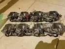
A further update. These arrived today!

lh3_googleusercontent_com_euuy77WacwWJSFzv1sDSL_F_pDhO4YPk2gQkdbe71ae2017eb22959ed11ed19a74195.webp

Coils from a Chevrolet LS1 or similar! Exciting because they can be triggered directly from low current/voltage. Giving the advantages that they can be triggered directly by the Megasquirt and they will introduce less electrical noise due to the low triggering current. And they are pretty powerful by all accounts. One coil per plug. I'll be setting them up in a wasted spark arrangement initially. Probably feed individual trigger wires through the bulkhead and just connect them to the ECU in pairs.

I'm thinking of mounting them where the original coil was:

lh3_googleusercontent_com_lhzm5SiL_HTTDiaZmjI1AUhPGR3obQJOS92P5f63dcfbe10a5fd244f97b0293f3419a.webp

But I am a bit worried about the strength of the shelf and whether it will support the new coils OK. I'm thinking of strengthening it above and below. The advantage is the packaging - I have loads of space... Will probably stack them on top of each other - two groups of three. Even the original HT leads will work (at a pinch), but will need to be rerouted. Could be messy to begin with.

It's getting a bit lonely posting updates without hearing responses!

I have another question... I dropped a bolt in the middle of the V. Ooops. I can't even see it to see where it went. Do I absolutely have to remove it, or can it stay there for ever more? Is removing the manifold a pain? I can see it's bolted to something by the turbo. How much has to come out from the turbo before I can remove the manifold? There's nothing left connected to the manifold any more so that bit's easy at least!

Still not decided which injectors to buy. The KnockTek knock sensor has arrived though, so that's good news.

I decided to remove the wiring that goes round the left-hand side of the engine bay. This is so that I can add the wires for triggering and powering the coils. The good news is that they'll travel a completely different route from the engine sensor wires, so that means less potential for electrical interference for the sensor signals as well. Interestingly enough, I was expecting the wires that run behind the turbo to be pretty crispy, but they appear fine! Everything's covered with the fine powder that was used when the car was soda-blasted during the previous owner's ownership. I got quite a lot out when I removed the loom!

Oh and the fiancee has told me she would definitely like to use the Alpine to go away in for our honeymoon. I guess I should count my blessings! Deadline September...

Andrew
 
Fortune favours the brave....................and you're brave. ww.renaultalpine.co.uk_images_smilies_icon_thumbup.gif

Keep it up, nice little project. I like your approach.
Good luck and carry on posting, there'll be plenty of people interested in your work.
Every days a school day.
 
Back
Top