r5gordini
Well-Known Member
A bit of background. I have had three fuel computers fail on me in about a year! The problem seems to be the LCD. I suppose it's just unrealistic to expect a 20 year old LCD, let alone one engineered by Renault, to work perfectly!
I got my thinking cap on and came up with the idea of using an Arduino single board computer to replace the Renault computer. After a weekend's work, I have come up with the following. So far I have just got the fuel gauge working. Next bit (mpg, trip, etc.) is a bit harder.
There are several advantages to this method of solving the problem:
1. Modern electronics: easily upgraded and replaced
2: Modern display technology: my solution uses lovely OLED. No backlight required!
3. Flexible: we can program and calibrate it to our needs. Different injectors? No problem. Different wheel diameters? No problem!
For me, a working fuel gauge is a must, which I have got working today. It still needs a bit of calibration. After that, I intend to add (in complexity order):
1. Temperature in degrees celcius!
2. Speed in mph. Average speed
3. Trip distance
4. Mpg
5. Miles left in tank
So how did I do it? Took an old 21 computer, desoldered the connection block:
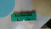
Soldered it onto some veroboard:
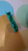
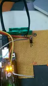
Did some wiring on the verobard to connect up to the Arduino:
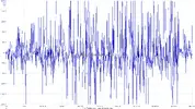
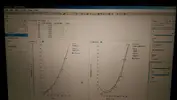
Wrote a bit of software to interpret the fuel sender's output. Graphed its resistance, working out an interpolated fuel reading. Used the software I use every day at work. Needs to be calibrated a but better but this is a rough start:
Um... Wired up the power pins and plugged it in!
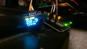
I am very happy about the result and am excited about the project. It's going to take me a while to get where I want, but I will keep going!
Sent from my HTC One_M8 using Tapatalk
I got my thinking cap on and came up with the idea of using an Arduino single board computer to replace the Renault computer. After a weekend's work, I have come up with the following. So far I have just got the fuel gauge working. Next bit (mpg, trip, etc.) is a bit harder.
There are several advantages to this method of solving the problem:
1. Modern electronics: easily upgraded and replaced
2: Modern display technology: my solution uses lovely OLED. No backlight required!
3. Flexible: we can program and calibrate it to our needs. Different injectors? No problem. Different wheel diameters? No problem!
For me, a working fuel gauge is a must, which I have got working today. It still needs a bit of calibration. After that, I intend to add (in complexity order):
1. Temperature in degrees celcius!
2. Speed in mph. Average speed
3. Trip distance
4. Mpg
5. Miles left in tank
So how did I do it? Took an old 21 computer, desoldered the connection block:

Soldered it onto some veroboard:

Did some wiring on the verobard to connect up to the Arduino:

Wrote a bit of software to interpret the fuel sender's output. Graphed its resistance, working out an interpolated fuel reading. Used the software I use every day at work. Needs to be calibrated a but better but this is a rough start:

Um... Wired up the power pins and plugged it in!

I am very happy about the result and am excited about the project. It's going to take me a while to get where I want, but I will keep going!
Sent from my HTC One_M8 using Tapatalk


