There is more to life with TurboRenault.co.uk

Register a free account today to become a member! Once signed in, you'll be able to participate on this site by adding your own topics and posts, as well as connect with other members through your own private inbox!

5 GT Turbo Vacuum, Boost and Fuel Pipes

M2YLE

Member
Hi,

Apologies if this has been covered before but I am looking for a bit of a help on the Vacuum and Fuel Lines to the Solex 32 DIS Carb / Inlet manifold if possible?

I am still trying to fully getting to grips with what goes where and am a bit lost as my car has been modified, partially dismantled prior to me getting it and becoming apparent there are parts missing.

My understanding is as follows:

Fuel
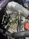
Tank > Pump > Filter > Regulator > Carb (Main Inlet is No. 2 in Photo Below)
Regulator takes a pressure feed back from the carb to increased fuel pressure with boost (not sure which No. port this should come from)
Regulator > return to Tank

Vacuum
Brake Servo takes a vacuum from the inlet manifold (No. 8 in Photo Below ?)

Boost
My car appears to have had the Cup MOD to the actuator as the 2 righthand lobster connections are blocked off?
AEI receives a input from the boost pipes to allow it to alter timing
(not sure which No. port this should come from)
Boost Gauge in Standard Clocks (not sure which No. port this should come from)
Aftermarket Boost Gauge (not sure which No. port this should come from)
Actuator - I think this should be a direct feed from the Carb as my car has had the Cup mod? (not sure which No. port this should come from)


To help me identify them I have taken some photos and numbered each connection and what I think these are for:

1. Should this be the take off to the Fuel Regulator?
2.Main Fuel Feed?
3.
4. Blocked Off
5. Water Feed to Carb
6. Water Outlet from Carb to Inlet
7. Water Inlet from Carb
8. Vacuum Feed to Brake Servo?
9. Water Outlet?
10.
11.
12.
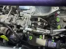
IMG_2398.webp

IMG_2399.webpIMG_2404.webp


Please let me know if I have any of the above wrong or if you can let me know what the missing ones on my list are for?

Thank you in advance!
 
1. Fuel regulator vac pipe and oem boost gauge.
2.Main Fuel Feed.
3. Acc pump, leave disconnected
4. Mixture screw, somebody has blocked with a bolt
5. Water Feed to Carb - leave disconnected
6. Water Outlet from Carb to Inlet - leave disconnected
7. Water Inlet from Carb - leave disconnected
8. Vacuum Feed to Brake Servo
9. Inlet water feed - leave disconnected
10. Actuator pipe takeoff when running cup mod
11. Aei reference pipe needs to go on here and any aftermarket boost gauges
12. Enrichment block overflow - fit a pipe leaving it open to atmosphere, its only there in the event of the diaphragm splitting
 
@Brigsy Honestly Thank you so much!

That has made it all so much clearer in my mind and not quite as daunting as it first appears when I look at the maze of pipes.

Just one more thing, in the box of pipes I got with the car I can see that one of the vacuum pipes looks to have a non-return valve, i am assuming this will go in the actuator feed pipe?
 
Also just for my information, do you know what the original purpose of the water feed to the Carb/inlet was?

Can't make up my mind if this is suppose to help cool or heat them to be honest.
 
Also just for my information, do you know what the original purpose of the water feed to the Carb/inlet was?

Can't make up my mind if this is suppose to help cool or heat them to be honest.
I think it was to try and prevent carb freeze in the cold weather by providing warm water to keep the carb warm
 
Thanks @andybond.

Lucky its always warm up here in Scotland! Well will be on the days this is out the garage.

That reminds me, my car doesn't appear to have a fan switch on the Alloy Rad, there is a proper Blanking plug installed where i would expect it to be. Could the fan be controlled elsewhere? or perhaps it was wired to a manual switch in the car?

One last thing that i find a bit strange that's been done to my car and i really don't know why. The reserve Fuel Tank has been removed (it came boxed with the car along with the filler neck and appears to be in perfect condition ). The filler neck on mine appears to have been changed to maybe a campus one and associated vent pipes all properly routed and fixed.

I can only think this was done for weight saving as the rear seats have been removed etc. or is there another reason I am missing?
 
Sounds like I shouldn’t be that concerned about getting it fitted back in. Car will only be used as a weekend toy so I’m sure it will still have plenty of capacity for what I’m needing. 👍
 
@Brigsy Honestly Thank you so much!

That has made it all so much clearer in my mind and not quite as daunting as it first appears when I look at the maze of pipes.

Just one more thing, in the box of pipes I got with the car I can see that one of the vacuum pipes looks to have a non-return valve, i am assuming this will go in the actuator feed pipe?
Any pics of the pipe with one way in? No valve in actuator pipe, sounds like the servo pipe as that has a one way valve in.

Remove the blanking plug on the rad and fit the fan switch in its place.
 
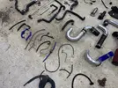
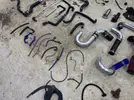
Here is a picture of the various vacuum hoses that came with the car.

IMG_2262.webp

You will see the valve on the blue pipe. Will most likely replacing all of these anyway but just wondered where it should go.

I will fit a temp switch to the rad, just thought it was odd it’s not there. Joys of working on a modified car.

IMG_2262.webp
 
Last edited:
That 1 way valve is for the brake servo, so it doesnt see boost under throttle. Make sure the valve is the right way! It should allow the manifold to create a vacuum in the servo, but not deliver pressure under throttle.
 
That 1 way valve is for the brake servo, so it doesnt see boost under throttle. Make sure the valve is the right way! It should allow the manifold to create a vacuum in the servo, but not deliver pressure under throttle.
Great thanks!

So the air travel/ valve direction is from the servo to the manifold (to create the vacuum) then the valve stops the boost returning. Makes sense!
 
I would sniff out some better reinforced hose for the vac pipe too as the blue silicone is not ideal.

Also worth binning the gplus water hoses for samco, roose or similar good quality replacements. The bleed nipples are poor on them, can see some have been repaired.
 
Yeah, they looked to have been epoxy’d. I actually thought they might have been added but obviously they must have been leaking at some point.

The servo has a reinforced pipe on it at the minute but no valve. So I will either fully replace or fit a non return to that.

Thanks again for the advice.
 
Thinking about this the one way valve is already on the gtt inlet manifold not in the pipe as standard, and you already have the reinforced vac pipe, so that pipe in the pic is probably part of the oem actuator setup which is not needed running cup setup.

Use the oem reinforced hose if its still fitted.
That’s perfect thanks. I think the blue pipes were used in a previous version of the car setup so that makes sense. There are still a couple of blue ones used though in out of site places. I will likely start afresh when going back together properly.
 
Back
Top