There is more to life with TurboRenault.co.uk

Register a free account today to become a member! Once signed in, you'll be able to participate on this site by adding your own topics and posts, as well as connect with other members through your own private inbox!

21 Turbo Renault 21 Turbo and Alpine A610 Fuel Computer issue/solution!

r5gordini

Well-Known Member
A bit of background. I have had three fuel computers fail on me in about a year! The problem seems to be the LCD. I suppose it's just unrealistic to expect a 20 year old LCD, let alone one engineered by Renault, to work perfectly!

I got my thinking cap on and came up with the idea of using an Arduino single board computer to replace the Renault computer. After a weekend's work, I have come up with the following. So far I have just got the fuel gauge working. Next bit (mpg, trip, etc.) is a bit harder.

There are several advantages to this method of solving the problem:

1. Modern electronics: easily upgraded and replaced
2: Modern display technology: my solution uses lovely OLED. No backlight required!
3. Flexible: we can program and calibrate it to our needs. Different injectors? No problem. Different wheel diameters? No problem!

For me, a working fuel gauge is a must, which I have got working today. It still needs a bit of calibration. After that, I intend to add (in complexity order):

1. Temperature in degrees celcius!
2. Speed in mph. Average speed
3. Trip distance
4. Mpg
5. Miles left in tank

So how did I do it? Took an old 21 computer, desoldered the connection block:
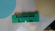
images.tapatalk_cdn.com_16_01_10_81d08ea375f93a6167834e257dc534cd.webp

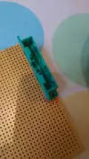
Soldered it onto some veroboard:

images.tapatalk_cdn.com_16_01_10_18700c66897aa03bb302e894e7dabe9f.webp

Did some wiring on the verobard to connect up to the Arduino:
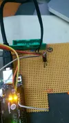
images.tapatalk_cdn.com_16_01_10_bc523c0da7404464a357c1353509d3c2.webp

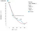
Wrote a bit of software to interpret the fuel sender's output. Graphed its resistance, working out an interpolated fuel reading. Used the software I use every day at work. Needs to be calibrated a but better but this is a rough start:
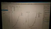
images.tapatalk_cdn.com_16_01_10_b95b9906a2f41ff34c532b0b970a347d.webp

Um... Wired up the power pins and plugged it in!
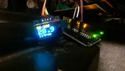
images.tapatalk_cdn.com_16_01_10_abf153fe996e436a916d7f6191ab8f3d.webp

I am very happy about the result and am excited about the project. It's going to take me a while to get where I want, but I will keep going!


Sent from my HTC One_M8 using Tapatalk
 
It's not counting injector pulses though is it. You would need to measure how long the injector pulses for in ms every time it pulses, and then take the per-second flow rate of (one injector * 4) and * by the cycle ms pulse size.
Example, OE 802's are 287cc/min @ 3bar IIRC, thats 4.78cc/sec.
Injectors pulse (batch fire remember) for 10ms
(4.78 * 4) * 0.0010 = 0.01912cc of fuel used per cycle (RPM) (not even allowing for injector dead time or fuel pressure variations)
Now if i'm at idle, at 900 crank revolutions per minute thats 450 injection events per minute.... 7.5 per second. At 6000rpm, thats 3000 injection events per minute, 50 per second.
You have to be able to measure, calculate, convert to Gallons or Litres and add to a total over 50 times a second and the faster it gets the longer the ms pulses are and the less time you have to calculate between pulses. Ain't gonna happen.


Probably best stick with an averaged level :)
 
Last edited:
Hehe! I can now report that the speed sensor is working! Well, it's working in that I can record the "clicks" of it, but there seem to be a lot more pulses than I expected and my speedo code doesn't work.
Somewhere in the archives I have the speedo drive ratio number that would make it easier to translate that clicking assuming it's once per revolution of the cable (I'm not sure if it is or not!)
Can you not count the clicks-per-second at a few different, constant speeds to extrapolate the linear line of clicks-to-speed? Should just be a simple line graph.
 
Ain't gonna happen.

Is , and does.

Works that way on the meg and @jamesy12345 OVLOV.

You create a table of preset figures for duration ( referenced by grid eg a7 )
You create another for flow ( as above )
You then have to store 2 variables in and can reference in a lookup at a later date. It would be stored in volatile memory. Only the committed mpg figure would need to be stored.

Easy peasy. ( almost ! )
 
Ain't gonna happen.

Well - that's how the existing code I have works, so it may well happen! Even though it sounds complicated ;-)

I will put the code in and then wire up the sender and see if I get something sensible! And yes, for speedo I will do something like you say. There's a bug in my code at the moment that never displays anything for speed - it was difficult to simulate the speed sensor on the "bench"
 
Injector duty cycle maybe? If you knew or assumed the duty cycle at different RPMs then that would give a flow

85% duty cycle at x-thousand rpm would give a flow of about 300 cc per minute per injector with 350cc injectors

Then sum of the area under the curve RPM based consumption against time? Or am I talking bollocks...

http://www.stealth316.com/2-calc-idc.htm


Ironically this would be a lot easier for an Adaptronic as I can bring the injector map grid up on screen and copy it to a table.
To be honest, i'd be happy with a direct read from the tank, sloshing about or not because its 1)better than I have now and 2)it wont flash irritatingly all the time because its in error without the feed from the ECU!
 
OK! Update time ;-)
I have managed to get a reasonable speed readout. Definitely needs calibrating though. I have also got the function selection to work, after a lot of faffing about. I will continue to calibrate the fuel gauge too!
I have also begun the physical installation - I have switched to an embedded Arduino - the Nano:
IMAG2279.webp
I installed the Nano on a daughterboard so I had freedom to wire up only the pins I needed. Although the Nano can accept up to 20v it might make the onboard regulator rather hot at 13.x volts from a car alternator, so I added my own regulator to step the voltage down a bit first.
Next job is to connect up the reset button and then work on storing a true "trip" rather than displaying instant readings as I am doing now. The code is all there - it just needs integrating and testing.
 
Right... An update on progress! I took the car out yesterday and measured the speed readout against GPS. Pretty good! I've had another go at recalibrating it today and it's even better. Pretty much bang on. More accurate than the original speedo, that's for certain. I am trying to engineer it to read a tiny bit fast, but it's pretty much spot on as far as I have been able to check so far.
Fuel gauge, not so good. The sender isn't showing overall consistent readings - it's very sensitive. The resistance can change a very small amount, which leads to a massive difference in the fuel tank reading - the range is only 0 - 350 Ohms anyway (0 is empty, 350 is full). I also took the car out yesterday and calculated that I had 16 litres at 267 Ohms. Today I took it out for a short drive and now it reads 281 Ohms, even though I have used some more fuel! I reckon the 267 reading may have been false. I am going to leave the car to settle for a bit then read it again.
When driving today (the first time I have had a "live" fuel reading), the fuel reading fluctuated wildly. And I mean wildly - from 11 litres at one point to 45 the next! It's not even good enough to sample it for an average reading. It's just totally all over the shop!
I think I need to update the fuel tank reading only when it's properly stable. The only time it's going to be reliable is when the car is stopped and on the level. I definitely think we need to measure the fuel usage by calculating it from the injector pulses. I know this will be different for Adaptronic - but anything is possible!
Another challenge is that the Arduino has very little RAM - it's only 2K so I have to be very careful with its usage. I can't store loads of values to calculate an average for example.
I can think of the following algorithm:
  1. Read the fuel sender 10 times, once a second
  2. If the results are all the same, mark the reading as "good" and update the display
  3. Otherwise, monitor the fuel usage and update the reading based on the last good reading minus the fuel used since the last good reading
It should work without the need for item 3, but the update frequency will be low. Looks like I now need to do the fuel injection readings - not got to that yet!
Dave - what can the Adaptronic signal in terms of injectors - do we get a pulse just like OE, or is it a different type of signal? The code I have reads how long the injectors were open. It should all just be a matter of coding for the different scenarios anyway.

The above is definitely progress!
 
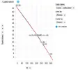
I figured it out! The fuel sender works the opposite way round from what I expected (or was led to believe by the Haynes manual). No wonder two readings looked ok but a third didn't make sense! And I made a typo (I think) in my Excel sheet, but not my code... Here are the measured readings I have so far:

//Calibrated:
//5.6G = 25.45l = 226 Ohms
//3.5G = 15.91l = 267 Ohms
//3.0G = 13.63l = 281 Ohms

So now to fix that in the code. It then leads to this picture of the calibrated fuel curve:

Calibrated fuel curve.webp
 
Thanks! I am still making progress, but the fuel gauge is a tricky one. Unfortunately the Arduino doesn't have enough RAM to store a large number of readings from which we can calculate an average, and the fuel gauge reading is not stable at all. Even when the car is sitting on the level. It's ok until you turn the engine on, then it fluctuates just enough. So we can't use the "display if there have been x consistent readings".
It gets even more difficult with memory when we start to store trips! Eeek...
I _will_ prevail.
 
Brilliant work!

@DaveL485 , are phase1 and phase 2 fuel gauge sensors the same, or different?
Between phase 1 and 2 there is an inversion somewhere. If you fit a phase 1 computer to a phase 2 the fuel level reads backwards. I don't know if the inversion is in the computer or sender though.

Also, Andy, the Quadra and 2wd tanks are different sizes/senders so we would need 3 calibrations potentially.... Phase 1 2wd, Phase 2 2wd and Quadra.

Is the Arduino thing essential for any reason? Could we swap to a Raspberry Pi or something? Is that overkill? Just lobbing ideas out there, the Pi has loads of RAM by comparison. We could average a lot more fuel readings then.

Adaptronic you have enough injector outputs to just wire one straight in. Are you defo reading the injextor pulse and not the trip feed from the ecu?
 
Interesting on all that! I have done some more playing and now have freed up a load of RAM - some of the code I imported was wasteful. I now have a whole 123 bytes spare! And that's even after averaging 10 readings.
The Pi is a bit overkill - it's much larger physically too. I am hoping to build something that's small enough to be plug and play.

Also, Andy, the Quadra and 2wd tanks are different sizes/senders
- eeek! I have lost track of which original fuel computer is which. I may be running on one that's not calibrated to my car, so I might run out of fuel (again)! The only proper way to do it is to run out of fuel and add known amounts and read the sender. Or we can just assume it's a straight line and measure before and after chucking a load of fuel in. My experiments so far seem to suggest it's a pretty straight line.

I assume it's injector pulse. My wiring diagram says injector pulse. Not yet wired up.

It's bedtime, so I'll update when I have more info.
 
I am now averaging 30 readings. Sampled at 0.5 second intervals (at the moment). It's just how often the display is refreshed in the main code. 103 bytes spare - that's enough to be working with for now. There's some further optimisation I can do to save some more memory when I finally tidy things up.
My current algorithm averages 30 readings and only updates the display of fuel remaining if the last 10 outputs were the same (from the average function). I haven't tested it on the road yet, but, with an average number generator that generates resistances in a 20 Ohm range, it seems to work pretty well, or at least is getting there! 20 Ohms is abot equivalent to 4 litres (I think - brain is on the blink now).
I can also put some code in that only ever allows the amount of fuel shown to decrease (once it has stabilised). That should damp down unwanted fluctuations in the fuel level!
 
I can also put some code in that only ever allows the amount of fuel shown to decrease
Pretty sure thats how the OE one works too.

You have really tweaked my interest with this. Considering playing with a Raspberry Pi for my car now, though i have a full windows 7 setup to go in there in a micro-ATX case with a 7" HDMI touchscreen for the Adaptronic and SatNav...maybe I could engineer something for that....can you emulate the OLED display readout?
 
Thanks.
What do you mean by emulate the OLED display readout? I think you could drive an OLED from the Pi. The Arduino is more suited to this project really - for example, it can read analogue sensors without additional electronics (Pi needs an A to D converter). It's also better as an embedded solution - it even uses small enough amounts of power that it could be left on permanently.
I tested the fuel gauge this morning. Works pretty well - just needs some optimisation. Am going to implement some code that only allows the reading to change by 1 litre at a time and also only allows the reading to decrease. It will assume you turn the ignition off when you refuel!
 
Back
Top