There is more to life with TurboRenault.co.uk

Register a free account today to become a member! Once signed in, you'll be able to participate on this site by adding your own topics and posts, as well as connect with other members through your own private inbox!

How (not) to make your Dauphine Handle

Electricity and water in the same place and time is bad, mkay...
IMG_20220210_161806471.webp

The bits arrived, it's back together and I'm reinstated as chief cook and bottlewasher

IMG_20220210_161818105.webp

Should have left it broken.......

The other Alp axle has gone to be cleaned, and I have been on a double secret job to adapt a BMW M3 gearbox to a one piece prop, I'm not writing this up as, I'm not convinced it will actually work. There is enough rubbish on this thread already!! However I did go to the bodyshop to have a look at @paule78 's 8 to see how its going, so you need to tune in to the other side...
 
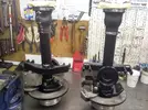
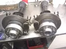
Moving swiftly along to the other Alp axleSteven Ward 17th Feb (2).webp

I did mention centrecaps didn't I ?

Anyway
Steven Ward 17th Feb (3).webp

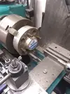
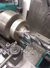
The 30mm drill is great fun.
It gets bored out to 53mm turned over and pockets put in for removal which I covered earlier

Cleaning up the parts for assembly revealed that shrapnel from the insides of the gearbox had managed to get into the Axle trunnion bearings which were duly stripped and washed

Steven Ward 17th Feb (1).webp

It must have been some shitstorm of stuff flying around to get inside these and it was a deep joy job cleaning off every one before re-assembling them
Have woken up to pissing snow which now seems to be easing, so might drag my ass to the workshop after lunch to finish them off. After that I have the output U/J's to re-centre and That's it, I have everything I need to build the box except the Crownwheel and Pinionshaft, which I hope to have resolved next week and inbetween that, I will be rubbing primer on a R8 Turboterrific. Does anyone else here remember Peter Perfect??
 
Today has finished off the axles, so they can be put to one side, I just need to find a 60-65mm Jubilee clip to finish

IMG_20220219_135842033_HDR.webp

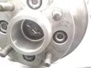
This is why no centrecaps

IMG_20220219_135940201.webp

Form follows function in my book

IMG_20220219_135944355.webp

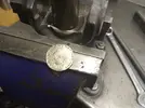
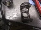
With that done I have stripped the U/J's and removed the 2 Franc pieces that were keeping the oil inside the box!!!!!

IMG_20220219_143727090.webp

The bar in the centre will be sliced and welded in to strengthen the inner half and ensure no oil leaks. It's too cold, so I've Jacked it in for the day

The ultimate sadness last night whilst waiting on the lathe machining bar ends I polished the Brancher on the 1700 with Grey Scotchy and washed it off with Brake cleaner, I hope it will look cool and multi- coloured after running in on the brake......

IMG_20220219_144526038.webp

More soon..............
 
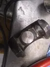
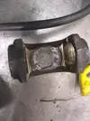
Today I stripped the other u/j and got a rather unpleasant surprise. They have been built with a staked type BMW centre which had machined caps fitted and welded. problem is that there is not really enough space for this and the welds were ground away until they were nearly transparent and the side that collapsed proved that particular theory. I was unsure whether to get new BMW centres and machine the yokes to take circlips or use my usual Alfa centres , problem is that one joint is virginal in the grooves department, but the other has had grooves part cut at Alfa centres. The difference between the 2 is about 20 thou each side, so enough to cause problems, decisions decisions...
With the 2 Franc pieces removed I made steel plugsIMG_20220220_193249941.webp

Better than 2F bits!!!

IMG_20220220_193300650.webp

This is better.

IMG_20220220_193306018.webp

Not the prettiest, but it has to be welded and you can't let the heat build up, as that causes other issues.
I'll phone Bailey Morris in the morning and check prices and availability, then make a sudden decision . Might as well have a pinch of excitement in an otherwise humdrum life.
More soon..........
 
I had heard the 2 Franc story, but it is actually true- not a great idea as oil travels up the splines and if it gets through the cap it goes everywhere.
 
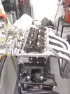
While I wait for my Increased abutment 24mm internal circlips to arrive, I decided to take the head off the 1700 and swap out the followers

IMG_20220301_145036873.jpg
Taking the Rocker gear off reveals the gauge plate shims fitted to raise the rocker gear up as the Twink valves are longer than the Std Renault items

IMG_20220301_145042810.jpg

You will also see the made up platforms for the Nissan valvesprings to get the opening pressure correct, plus titanium caps and Mini Cotters

IMG_20220301_150753241.jpg

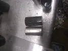
The Forged steel item (light) and the standard chilled iron which I had Nitrocarburised (tufftride)

IMG_20220301_151345496.jpgIMG_20220301_151345496.jpg

These are the largest valves that will go in without touching the liner edge

The other little custom mod I do to these is to bore out the dizzy hole in the head parallel to the Dizzy body

IMG_20220301_151404581.jpg

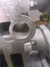
This allows you to remove the dizzy drive gear without taking the head off. These can be a problem and wear prematurely

IMG_20220301_151630209.jpg

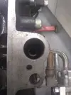
There are several little custom mods to this motor, this one is to allow access to the vernier timing gear, so the cam timing can be adjusted without taking anything apart. A real pain in the Ass to make thoughIMG_20220301_151715832.jpg

More soon.
 
Last edited:
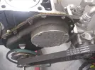
Couple of posts back, pic of toothed belt on front of crank......?
Is this motor dry sump? I assume that's an external oil pump?
Or is it fancy water pump? I'm intrigued...
 
@Turbell . Yeah its the dry sump system. I was fed up of the price of complete oil pumps and overhaul kits are not bad, but not great either, so I decided to sort it once and for all. Not a cheap solution either, but we now have 3 pumps in parallel 2 scavenge, 1 pressure. The 2 scavenge outlets are Siamesed together on the route to the cooler. The idea is to create a vacuum inside the engine when running as it should liberate a couple of hp. Will find out how well it works soon...
 
Back on the 1700 . The gasket set arrived, so I put it back together again
IMG_20220303_214801491.jpg


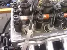
Forgot how much of a pain it is to adjust the valves, even with the special tool, because of the spacer tubes instead of springs, so no sideways movement

IMG_20220303_214809254_BURST000_COVER_TOP.jpg

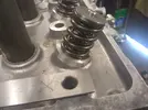
You can see clearly how much smaller the springs and caps are compared to the originals in this pic, in an effort to reduce the harmonic mass. I had bought some 1mm over length pushrods for using with reground cams. I wish I had fitted them to the Exhausts as the longer inlet valves need the pedestals shimmed up which puts the adjusters nicely in the centre of their adjustment range, but the exhausts are out the fully screwed in end, once again the spacer tubes prevent them being changed in situ....
More Soon
 
Time for the Sunday sermon
I am trying to get this motor ready for the Dyno. It is coming along and I am down to the last couple of jobs, problem was I could not remember if I had set the final Cam timing or not. I knew it would be close, but close is not good enough for this kind of application.
The normal method with a single cam is to set the cam at full lift on the inlet valve at the cam grinders setting, in this case 106 degrees after TDC, seems simple enough, but the issue is using a DTI on the piston crown will show you how there is a couple of degrees leeway at TDC, Fair enough when I built the motor I was sure to measure it both ways and split the difference to Get the TDC marks as accurate as possible. The big issue is that it's a full race cam, so it has a flat top, and the DTI on the inlet valve will not move through nearly 20 degrees of crank rotation, so where exactly is peak lift??? Therefore my preferred method is the one used by Dave Vizard, Dave Walker and Salv Sacco. It fits for any symmetrical single cam and is deadly accurate, no more trying to find the middle of he dead zone. What you do is fit 2 digital DTI on the Inlet and Exhaust valve caps on no 1 cylinder you fit them with their plungers at 90% of their full stroke and having put them into imperial measurement you zero both with No 1 cylinder firing, that done you rotate the engine 1 revolution back to TDC, on overlap the cam should be straight up at this point, meaning the same lift should be showing on the inlet and exhaust valves and because you are measuring on 2 flanks there is no dead area.
The trick here is that actually you don't want the same reading on both gauges, you want about 10 thou more lift on the inlet meaning the cam is advanced about a Gnat's Chuff. When the motor is mooing on at about 8000RPM and the top of the motor is straining to keep up with the bottom and the chain is stretched ever so slightly the cam timing is bang on. No Error

IMG_20220306_195003033.jpg

SO where did it end up ??
I had it at 142 thou on the Ex. and 151 thou on the In. 9 thou difference close enough, so I made sure the vernier was tight and that's it..

IMG_20220306_194953079.jpg

End of Sermon............
 
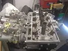
I was not too happy with the throttle linkage, so had to bite the bullet and buy a new one, went with the Webcon LP2500 which works the right way round for my application . The R5 Head has it's inlet ports quite close together and you can't get the spindle nuts off without removing one carb, so here we go again.

IMG_20220309_144923215.webp

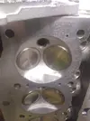
With That done it seemed a good idea to take a picture looking down the port


IMG_20220309_144934006.webp
It's all back together again and I'm happy with it, no doubt I'll recover from the cost of the bits........... in time..
I forgot to take a pic, but I'll get one tomorrow
 
Back
Top