There is more to life with TurboRenault.co.uk
You are using an out of date browser. It may not display this or other websites correctly.
You should upgrade or use an alternative browser.
You should upgrade or use an alternative browser.
How (not) to make your Dauphine Handle
- Thread starter Steve Swan
- Start date
Steve Swan
Well-Known Member
Right Here goes.
It is difficult to get a clear picture in your mind in reference to what your car does geometrically in a corner. Photographs from the Racetrack can be very helpful, but there is no substitute for actual measurement. I actually built a half sized string computer from Alan Staniforths Race and Rallycar handbook. It was to see what (if any) improvements could be made by playing with any of the inboard pickups. This was partly academic as being a crossmember type there is not much scope for movement. What it revealed was that nothing much could be gained by moving these pickup points around, but it also showed that the suspension produced a small increase in negative camber on bump and reduced it on droop. string experiments on moving the bottom arm down in or out only gave negative results (wrong camber changes and terrible scrub which is actual track change and is to be avoided if at all possible). Answer is to leave as it is
My Dauph has a custom Titan rack in it as I needed a quickrack. This has the same length rack bar and travel as original, but has a different body requiring different mounts. Having learnt the hard way with the 8G which also had a Titan rack, I took the opportunity to machine the R8/10 crossmember mountings to allow some adjustment before welding it into the shell. I hoped it would be enough, looks like I am Wrong yet again!!!
Back to the subject: What we need to do by adjustment is to harmonise the arcs of the upper and lower wishbones and the steering arm to give the required results, namely a slight increase in negative camber on compression, a slight reduction in Neggy. on droop, with preferably no change in steering angle if achievable. I had a mystery issue with my 8G which was that it was very nervous on undulating surfaces which was traced to 20mm of bump steer. It took an age to sort and I had to make some tools to achieve it, but I was triumphant in the end, and best of all the handling was very nice no nervousness at all, but mega turn in if required.
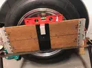
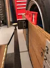
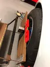
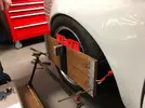
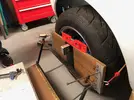
Pictures time again this sequence shows the gear being attached to the front wheel this allows simultaneous measurement of camber change and steering angle change. The only other special tool is the floormop which is used to jam the brake pedal on so the front wheel cannot rotate during measurement.
Pic 1 shows the scaleboard fitted to the wheel with the spirit level showing it is level (there is a centre pin on the board which is lined up with the centre of the hub dustcap)
pic 2 Shows the camber gauge on the scaleboard (an electronic protractor which must be zeroed against a known vertical surface) This is why your workshop floor needs to be level
Pic 3 Shows The whole shabang set up on rideheight and zeroed on all axis (the pointer an old R12 pushrod carries the weight of the gauge and makes it compensate for camber thrust) leaving the clock gauge spring to measure the change in steering angle only)
Pic 4 shows the front end on 2 inches of compression
Pic 5 shows it on 2 inches of droop


Steve Swan
Well-Known Member
What did I learn ? Quite a lot all of it BAD
The car was displaying more camber change than I would like, and there was a lot of bumpsteer, and in the more Dodgy direction, meaning as you turn into a corner the car will automatically turn in a bit more, this would probably manifest itself as an uneasy feeling of transient oversteer that would come to nothing, but would be unnerving at high speed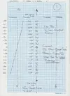
The car was displaying more camber change than I would like, and there was a lot of bumpsteer, and in the more Dodgy direction, meaning as you turn into a corner the car will automatically turn in a bit more, this would probably manifest itself as an uneasy feeling of transient oversteer that would come to nothing, but would be unnerving at high speed

Steve Swan
Well-Known Member
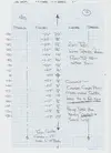
What to do I hear you ask? Well the bumpsteer is a bit of a bugger, but the rate of camber change is too high it needs to be tackled first , so as I had put a distance piece in under the top wishbone rod end, I decided to remove this and try again . This meant that I had lowered the outer end of the wishbone by about 5mm
Put it back together and test again
Put it back together and test again

Steve Swan
Well-Known Member
Steve Swan
Well-Known Member
Steve Swan
Well-Known Member
Steve Swan
Well-Known Member
That's it my Head is Burst! Giving up for the night ! please let me know if you want me to continue with this as it may take some time and I may lose my sense of reason before a conclusion
NIGHT ALL
NIGHT ALL
Turbell
Well-Known Member
Agreed, all gold, I bought a book on chassis and suspension so i could at least try and understand principles, I wouldn't really apply much of it as I'm not a track driver, the 750 is way, way off ever being a car that will handle, kingpins and swing axles don't really lend anything there.
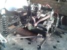
I did get rid of any play i could, tracked the car 4 wheel in line with string, touch of toe in at the front, and modified the leading arm existing ideas ( no room for trailing due to tank ) to something approaching a better solution of dealing with the swing axle problem, I'm interested how you tackled this and how you rate my set up, although I was aiming for cruising stability, bearing in mind the death inducing weave that 4cv's exhibit above 50....I'm reasonably stable now ( the car.....not me ) having rid the car of rear wheel steering, although it feels more eager to cock a rear wheel if i get a bit fruity on mini roundabouts or tight turns.
Pic of rear leading arms with rose jointed ends below, pick on back plates to a new rear crossmember with the pick ups as far inboard as I can get them to triangulate the swing axle tubes.

Steve Swan
Well-Known Member
@Turbell . To be honest you have got the back end as well tied in as is possible in the circumstances. I guess you tried it out without the spring to check it didn't bind up on its arc of travel, which means it is dandy. I see that you did get the trailing end of it as near to inline with the trunnion bearings as is possible which is key to successful operation.
The 4CV has a head start on later rear engined stuff by having the box bolted to the crossmember none of that gay rubber pads nonsense here. I have changed tack on the Dauph from the 8, The 8 had the box bushed into the crossmember and the trailing arms were rosejointed like yours. The Dauph is using standard trailing arms with the original rubber bush replaced by a homemade Nylon/stainless bearing, so it can only rotate and not waggle around, the top box mount is standard with 1k polyurethane filling to make it as stiff as possible and now has Mecaparts new side mounts, as @paule78 bought some for me to use on his 8 and I thought they were good, good enough to buy some myself!! ON both cars the standard engine crossmember and mounts went straight in the bin and both cars use a square tube triangulated crossmember with Gr4 escort world cup bushes. this means the engine is fixed in, up-down and sideways, and as the engine is bolted to the gearbox on these cars it is an unwitting part of the rear suspension. Looking at your photo you could do away with your engine mounts and use bushes there which would tie the motor in firmly, giving you the bestest 4CV back end in the world
Have you thought about a cheeky wee telescopic damper through the centre of the spring? Looks like there is just enough room. I guess you have brackets to attach one on somewhere else.
Set up is the key, that is why I am doing this article, my 8 with all its go faster bits was quite dire to drive once I learned to get them all working together it was a different car. Compared to my mate's Mk1 RS2000 (which was a good 200bhp car I double drove with him on a couple of races) it was like a Lexus. It was possible to take it to its practical top speed of 130mph and it always felt benign
Back wheels lifting on swing axle cars is not a good thing, coz its always followed by a complete spin or 1/2 spin, been there done that, in public too, most embarrassed I can tell you. That will be the closing part of this article a few months up the road when I make the Z bar for the Dauph. As Fred Puhn puts it in his excellent 'how to make your car handle' make one of these for your swing axle car even if you only go to the shops!!
play nice
Turbell
Well-Known Member
@Steve Swan
As the rear rose joints are not exactly in line with trunnions, geometry would dictate it binding eventually as you know, but with a little play in trunnion bearings ( although I mic'd up several sets of needles to get them as plush as poss) it doesn't bind in its max travel, i went as far as it would be coil bound and it felt fine.
Some dampers to replace the limiting rods inside the springs were a ' gunna' but stalled when my mind moved on to other cars......need to measure up and have a look see, being further out board than the inclined OE push bike pumps on the car ATM, think they'd be a good shout, I did consider some motorbike coilovers, then I'd have some preload/damping adjustment, although it would be a OE spring off job to adjust.
I've hardly driven it this year, retrimmed it and added some gauges other than that, it's just sat, need to sort at least one front drum cos it's egg shaped.
Perhaps I need to get back to this, rather than buy more shit......ooooops too late......
Steve Swan
Well-Known Member
ooooops too late ??? New thread Starting soon ???
Steve Swan
Well-Known Member
Steve Swan
Well-Known Member
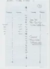
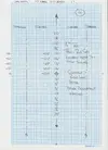
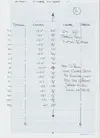
Tonights adventure was a shorter affair, still without a breakthrough. I moved the rack up as high as the slots I put in would allow and reset it all up and travel checked it again. The upshot is that this significantly reduced the bumpsteer, but there was another problem that showed up. The rod end on the top arm is getting perilously close to binding up at full droop. This means that I need to put a small spacer back in to the top arm, this will bring back some of the travel induced negative camber increase, which if I am thinking correct will remove the outstanding bumpsteer and hopefully get it to change to reducing steering on bump rather than increasing as it is at the moment
This means an hour or two in the workshop tomorrow making a few tapered spacers
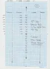
For your information All the steering numbers are negative above zero and positive below and I should have said that the numbers are thousanths of an inch , meaning that in the sheet below you can see that the total steering movement is now 350 thou or about 8.5mm this then has to be doubled for the other side 17mm of unwanted steering is unacceptable and will cause some very unnerving sensations behind the wheel.
I am aiming to have the total deflection between 1 inch up and 1 inch down to be less than 60 thou 1.5mm that should go unnoticed
Wish me luck! More soon

Steve Swan
Well-Known Member
Had a long hard think and had a bit of a Eureka moment. Dug through some old pics of the 8 and it never showed having too much negative camber on the front end in hard cornering, this led me to think that I had been hasty in removing the top wishbone spacer to reduce its rate of change. If you cant really see it on the test sheets what is happening is that the steering arm is shortening its arc quicker than the top arm causing the car to steer more as it rolls in and less as it rolls out. Also there is a lot of castor and KPI in this chassis which was designed in to Give stability in an inherently unstable design. this means that there is a lot of camber change as steering is increased . What if it is still just not enough? Put the top arm spacer back in (the one I removed in Step 2) and hopefully both arms will be shortening at at a rate much closer to each other, so tonight I did just that and......................................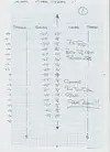

Steve Swan
Well-Known Member
You Dirty Fekkin Bar Steward!!!!!! Typical. I had wrongfooted myself at the start, and had been trying to fix something that would not be fixed. The more observant of you, or anyone still awake will have noticed that we have crossed the median line and positive has went to negative and vice versa. Hooray something has actually worked as I hoped it would. A 350 thou error down to 94 thou, and as we have crossed the theoretical centre the thing to do would be to pack up the outer rod end, so 1 standard M14 washer fitted approx 1.2mm lift on the track rod end and Boof total error down to 13 thou and in the important 1" up to 1" down window the total Error is 4 thou
So there you have it a total axle error of some 25-30mm at worst down to 4 thou on 1 side. hopefully I will get the total error sub 10 thou Perseverance is the name of the game that and being too bloody minded to give up
Just need to refit the spring /damper and do the other side using the same set up should hopefully be 1-2 washers away from where I need to be
In other news one of my refurbished (by me) Gotti's has been behaving beautifully for 4 weeks now has decided it does not want to hold air anymore and is leaking out just as fast as I can put it in. There's always something.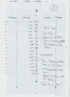

DaveL485
Staff member
Mixing metric and imperial is against the law!a total axle error of some 25-30mm at worst down to 4 thou on 1 side.
Similar threads
- Replies
- 8
- Views
- 191
- Replies
- 3
- Views
- 93

