There is more to life with TurboRenault.co.uk

Register a free account today to become a member! Once signed in, you'll be able to participate on this site by adding your own topics and posts, as well as connect with other members through your own private inbox!

5 GT Turbo EFI - GT Turbo

I'd be screwed otherwise.
You'd get there, it'd just take a lot, lot longer. When I picked up my first Adaptronic, the E420B in 2005 it was one of the first units on the UK and nobody had a scooby. I remember a few of us sat around outside my garage in 2005, 2006 ish looking at this big pile of wires realising how out of our depth we were trying to figure out trigger patterns LOL
 
image.webp image.webp Header/expansion tank finally fixed in place, good old JB Weld did the trick.

I've now got the correct hoses, they just need cutting to size. Steel connecting hose should arrive today. Will then have bung welded in for temp sensor.
 
Yeah should work well, the throttle cable ends should arrive tomorrow/Thursday.

Regarding FPR, do you think I should just set fuel pressure with gauge so I know its spot on and then remove and replace with the threaded blanking plug that came with FPR? Shouldn't be a problem once it's set to the correct pressure should it?
Either way, doesn't matter. Id probably keep it on for now as I have known aftermarket regs to go out of adjustment. I use OE regs as upping the fuel pressure over 3bar does very little.
 
image.webp So an absolute school boy error discovered today. I didn't even connect ECU (MAP) sensor to inlet, it's a wonder it even fired up.

Will get home tonight and connect up.
This is how it sits today :-(
 
So as expected, piped up MAP sensor to inlet. Set fuel pressure and idle screw and fired up and happily idled at 11afr (bit rich but only base map)


Will hopefully have all finishing touches done by weekend.
 
Very pleased Andy.

I just hope it delivers in all the ways I want it to, I am sure it will as I've heard nothing but positive things about Adaptronics. Looking forward to getting all the other bits and pieces tidied up. Will then get booked in with Chris, get some use out of it for rest of summer and then get some of the rough bits of bodywork taken care of during the colder months.

As it stands in its current spec if I can get a genuine 220hp but nice and smooth with a great set up ill be chuffed. Carb seriously did my head in. ;-)
 
image.webp image.webp image.webp image.webp Not a great deal done today. Still waiting for a few things to arrive and my friend Mark to come back this Saturday to add boost control solenoid and ISCV.

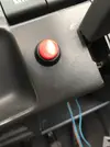
I did manage to remove the old fuel pump switch wiring as well as the panel that used to house fan switch, pump and horn. (Previous owner bodge). For the time being I've attached fan switch to left of steering wheel where there was already a hole and the same for the previous owners red horn button. Plan is to link the fan switch up to ecu at some point (I'm sure this is feasible)

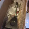
Planning to fit the Pure Motorport shifter tomorrow evening.

I'm having a couple of teething issues, currently after a couple of minutes of being connected to ECU and monitoring live data I seem to lose connection as live data screen freezes. I'm not yet sure if this is a USB cable fault or whether it's the laptop, ecu or software. I'll start by trying a new USB cable tomorrow.
 
Wire the fan control to the ECU, let it control the fan for you. I'll do a wiring diagram if you want but basically:

(Low current)
Batt + to fuse to relay pin 1
Relay pin 2 to Aux output (x), configured in WARI as "Water Temp", you can then choose the temp it turns on and off (in my case on at 94° off at 92°)

(High current, 30A)
Batt + to fuse to relay pin 3
Relay pin 4 to rad fan +
Rad fan - to Earth

I also configured WARI to turn on the yellow LED on the ECU unit itself, I can see the ECU where its installed so I can see the LED come on when the fans activate. You could set up a remote light on your dash if you wanted to though. You can also put in a T wire off the [Relay pin 2 to Aux output (x)] wire to a switch and then the other side of the switch to earth to give you a manual override if you wanted one.

Note: You MUST use a relay as the fan is too high current to use the direct switched earth in the ECU
 
One question I do have for you Dave is how many additional extras can I add to the ecu?

Bearing in mind I'm adding boost control, ISCV and now fan control - do i have enough physical capacity to link fan to ecu? I seem to remember from Scoffs install guide that aux outputs had to be used for a both boost and idle valve.
 
Last edited:
You have eight Aux Outputs, now dont quote me but IIRC the first 4 are high current (Max 3A) and 3 of these PWM capable with selectable frequency (23Hz – 2kHz). You want to use the high current PWM capable stuff for IACV and Boost control.
The low current I think is only 200mA, so you use these to drive relays and maybe small LED lights. I was going to try a little staged shift light like F1 cars have using my spare low current aux outputs 6/7/8.

I have four set up:
Aux1: Idle control, PWM 25hz
Aux2: Water Temp, Hi threshold 94° Lo threshold 92° (activates 94, deactivates 92...this on/off gap is to allow for sensor noise etc)
Aux3: Wastegate, PWM ??hz. (This is the MAC valve)
Aux4: Fuel pump relays (Simple on/off)

I could move water temp and fuel pump to low current 5-6-7-8 if I needed the high current or PWM capable AO for something else, but currently (lol) I don't.

For info, PWM is Pulse Width Modulation. Its a method of getting analog results with digital means....

The Internet said:
Digital control is used to create a square wave, a signal switched between on and off. This on-off pattern can simulate voltages in between full on (5 Volts) and off (0 Volts) by changing the portion of the time the signal spends on versus the time that the signal spends off. The duration of "on time" is called the pulse width. To get varying analog values, you change, or modulate, that pulse width. If you repeat this on-off pattern fast enough with an LED for example, the result is as if the signal is a steady voltage between 0 and 5v controlling the brightness of the LED.

Same principle for the IACV and boost controller, the modulated digital signal "turns up" or "turns down" the controlled units in accordance with the ECU parameters that you will have oh-so-much-fun setting up.
 
Interesting fact: Hz (Hertz) is defined as "Cycles per second". The 420d main loop runs at approx 400Hz, meaning the main calculation loop to run your engine processes four hundred times a second :)
 
Awesome stuff Dave, all very useful.

I'll get my wiring guru to add in the fan to loom and then come back to you re setting temp up on Wari.

As a side note I swapped the USB cable for my GoPro one and it reads live gauges perfectly so was obviously the cable.

I've lowered idle ever so slightly to 900rpm and when up to temp idle afrs are sitting at 13.3 so much better.

With any luck the throttle cable spindles will arrive in the next hr or so.
 
Dont forget you can test the AO setup when its wired in with the F11 window, Aux Output Override/Enable/Aux(x), its in the video I sent you on FB. Saves you trying to get it up to temp to see if the fan activates.
 
Back
Top