There is more to life with TurboRenault.co.uk
You are using an out of date browser. It may not display this or other websites correctly.
You should upgrade or use an alternative browser.
You should upgrade or use an alternative browser.
5 GT Turbo My C1J Forged build
- Thread starter Fordy
- Start date
Fordy
Well-Known Member
Actually believe it's nearly 99% fixed.
I've found my megasquirt was a old kit years ago and been battling poor components since the beginning
So last night I changed my br9es out for br7es as I've found you can foul plugs on overrun - this gave a noticeable difference.
Then I changed the VR circuit chip to the latest type as the LM2904 is well known for issues, it signal runs up to 3.5v. The new chip runs all the way up to 5v.
Now I've had very very little stuttering!
The car is mucho quicker aswell and seems like it wants to rev a lot more easier, before it didn't feel like it wanted to rev that high .
Twice today I've hit silly speeds with relative ease, 120 this morning trying to bait a R33 gtst and lunch time up to 110 just overtaking.
Considering building a fresh megasquirt board now with only the circuits I need on the board
Fordy
Well-Known Member
so datalogged on the way home to get a boost plot at 55% to 65% boost duty
ecu is sensing 22psi so i need to check the mechanical gauge is accurate as its quite old.
upgraded to megalog viewer HD and now the boost plotting is so easy to see, also a spark plot to see where its actually running in the map in seconds
ecu is sensing 22psi so i need to check the mechanical gauge is accurate as its quite old.
upgraded to megalog viewer HD and now the boost plotting is so easy to see, also a spark plot to see where its actually running in the map in seconds
Attachments
Fordy
Well-Known Member
I guess so, but I'm picking up on so many little problems etc
Earth problem in the car behind the dash, door lock was slow no longer works,
Dash is pushed out as the loom is a mess behind.
Ideally I want a new uncut dash loom but my guessing is they're no longer available
After whacking some timing in the idle areas I can now pull away better without big revs, this TTV flywheel and paddle is aggressive, clutch grabs and the engine doesn't have enough torque to battle it at 10 degrees, 18 degrees seems fine ATM
Going to pull the accel jet out and clean it incase that's got the same residue that I found in the enrichment block which I'm assuming is from the long stint of storage
Fordy
Well-Known Member
Time to bump this up.
We’re officially going full efi.
Adaptronic M1200 and loom has arrived thanks to Chris @ Efiparts.
I’m new the owner of Mark Davis manifolds.
First job is to get the inlet manifold fixed, i am handy with a mig/tig welder with some certificates in mig welding.
I’m not keen on the idea of welding the pressurised fuel rail tho.
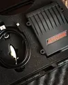
So the inlet manifold saga.
In order from top to bottom. The injectors are 1-2-3-4
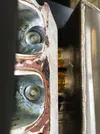

And the fuel rail fixings 1 was damaged so I helicoiled it and it worked fine.
Thought might aswell helicoil the other one for strength...... and the bore was so deep it quickly cut through into the fuel chamber and thus it’s now scrap as 3-5bar vs a bolt thread over a hot manifold isn’t my style.
So the plan of attack.
Use the current fuel rail as the spacing is right, cut out the existing injector ports as they’re obviously cut back too much but also a bit to loose for sealing.
I’ve got some injector bores premade from a previous idea of efi on a stock manifold.
Using 4 lengths of copper i’ll make some “fake injectors” to work as heat absorbers and for lining up the bungs perfectly
If the flanges warp the local engineering place have some nice gear but obviously have to skim both the inlet and exhaust flanges to the same
We’re officially going full efi.
Adaptronic M1200 and loom has arrived thanks to Chris @ Efiparts.
I’m new the owner of Mark Davis manifolds.
First job is to get the inlet manifold fixed, i am handy with a mig/tig welder with some certificates in mig welding.
I’m not keen on the idea of welding the pressurised fuel rail tho.

So the inlet manifold saga.
In order from top to bottom. The injectors are 1-2-3-4


And the fuel rail fixings 1 was damaged so I helicoiled it and it worked fine.
Thought might aswell helicoil the other one for strength...... and the bore was so deep it quickly cut through into the fuel chamber and thus it’s now scrap as 3-5bar vs a bolt thread over a hot manifold isn’t my style.
So the plan of attack.
Use the current fuel rail as the spacing is right, cut out the existing injector ports as they’re obviously cut back too much but also a bit to loose for sealing.
I’ve got some injector bores premade from a previous idea of efi on a stock manifold.
Using 4 lengths of copper i’ll make some “fake injectors” to work as heat absorbers and for lining up the bungs perfectly
If the flanges warp the local engineering place have some nice gear but obviously have to skim both the inlet and exhaust flanges to the same
Mark Davis
Brapmaster extraordinaire
Hope you sort it mate. Look forward to your progress.
Fordy
Well-Known Member
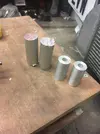
Made a start on making the new injector bungs.
19.9mm outer diameter, about 0.5mm bigger than current ones.
8mm internal.
Found some older injector bungs I made and tested trying to drill out from 8mm to 10mm using my drill press, bore started cutting centre and then at the other end was well off centre.
So the plan currently is to,
die grind/cut out carefully the current injector ports
Use current fuel rail for injector spacing.
Tack in place the bungs at the best angle vs fuel rail clearance
When happy weld bungs totally .
Take to local engineering shop to get bungs drilled out from 8mm to min 13.2 to a max 13.5mm as would rather have tight seals than loose.
Also get the shop to copy the fuel rail spacing using their machines.
Pretty boring update but progress either way

Fordy
Well-Known Member
Got a break this week so made a start back on this inlet manifold
I was going to die grinder it out but I ended up using a die grinder airsaw and a mini belt sander an. Then I looked like an aluminium snowman.
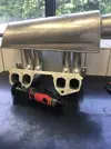
This is roughly the old injector angle but getting the injectors and fuel rail in and out was an utter joke as Mark can vouch for.
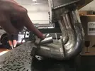
My new injector angle will be more like this so the rail and injectors tuck into the bottom of the inlet/running pipe area, should allow easy injector/rail removal
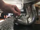
I’m going to say one thing my aluminium welding isn’t the most show worthy but my header tank hasn’t exploded yet nor the coolant temp sensor boss cracked off although that’s steel tig welding.
It’ll probably buckle the flange but live by the sword die by the sword mentality atm with this
I was going to die grinder it out but I ended up using a die grinder airsaw and a mini belt sander an. Then I looked like an aluminium snowman.

This is roughly the old injector angle but getting the injectors and fuel rail in and out was an utter joke as Mark can vouch for.

My new injector angle will be more like this so the rail and injectors tuck into the bottom of the inlet/running pipe area, should allow easy injector/rail removal

I’m going to say one thing my aluminium welding isn’t the most show worthy but my header tank hasn’t exploded yet nor the coolant temp sensor boss cracked off although that’s steel tig welding.
It’ll probably buckle the flange but live by the sword die by the sword mentality atm with this
Mark Davis
Brapmaster extraordinaire
Good luck mate, hope it comes out well.
Fordy
Well-Known Member
Mock up without any tacks
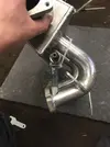

Looks good until you look at this angle. Will need fair few multiple passes on the tig to fill that void and is most certainly without doubt going to warp it.
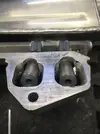
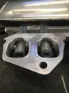
But I refuse to have the injectors at the stupid right place it was before.
Need to sleep on it and think before I zap it together


Looks good until you look at this angle. Will need fair few multiple passes on the tig to fill that void and is most certainly without doubt going to warp it.


But I refuse to have the injectors at the stupid right place it was before.
Need to sleep on it and think before I zap it together
Fordy
Well-Known Member
Well that went horrible wrong just tacking it 
Seems my tig has taken a shit on me instead of melting nicely the arc is just all over the shop, weirdly I thought this on the last cracked wheel I did. oh well never mind.
So I’ll just send it back to Matt for new runners and flange
Seems my tig has taken a shit on me instead of melting nicely the arc is just all over the shop, weirdly I thought this on the last cracked wheel I did. oh well never mind.
So I’ll just send it back to Matt for new runners and flange
Jesus the 2nd
Active Member
Hey hey!
I'm awaking an older topic here, but really like it espeecially the firs page (because I'm in the middle of a similar build )
)
I just have a question maybe someone here will know.
These wossner pistons, in which direction / orientation do they have go into the engine, which side to the flywheel?
On Original pistons there is a mark, but its not clear for me with the Wossners...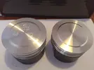
Left original tarabusi / Right a Wossner
Bottom of wossners, is that a mark? if so to which side does it go ito the engine?

Greets, Jasper / Evil Jesus
I'm awaking an older topic here, but really like it espeecially the firs page (because I'm in the middle of a similar build
I just have a question maybe someone here will know.
These wossner pistons, in which direction / orientation do they have go into the engine, which side to the flywheel?
On Original pistons there is a mark, but its not clear for me with the Wossners...

Left original tarabusi / Right a Wossner
Bottom of wossners, is that a mark? if so to which side does it go ito the engine?

Greets, Jasper / Evil Jesus
Jesus the 2nd
Active Member
I have sent them a mail, lets see if they answer otherwise Iĺl grab the phone indeed!The gudgeon pin is central, so i dont think it will make a difference which way they are fitted, give wossner a call to confirm though.
Jesus the 2nd
Active Member
Thanks for the picture! Now i can always install mine the same as your working enginepretty sure it doesn't matter tbh unless i've forgotten why mine are in how they are
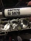
Here a picture of how mine are fitted and also the best engine sealer in the world, if you dont want a leaky C1J that is the stuff to use.
View attachment 148893
And a nice tip for the loctite, but aren't c1j's suppose to leak so you are sure there is still fluids in em?
Jesus the 2nd
Active Member
The gudgeon pin is central, so i dont think it will make a difference which way they are fitted, give wossner a call to confirm though.
I have sent them a mail, lets see if they answer otherwise Iĺl grab the phone indeed!
Just for you info, i got an answer from Wössner see below:
------------------------------------------------------------------------------------------------------
Hello Jasper,
you can assemble the piston in both directions. The piston don’t have a pin offset and is symmetrical in dome shape. Because of that there isn’t any mark on the piston.
The cavity on the bottom side is only for fixing the piston in the right position by the production process. So it doesn’t matter for you.
Regards
Dominik
-------------------------------------------------------------------------------------------------------------------
Similar threads
- Replies
- 2
- Views
- 282
- Replies
- 4
- Views
- 367
- Question
5 GT Turbo
What Wheels work for GT Turbo / Opinions
- Replies
- 1
- Views
- 134
- Replies
- 2
- Views
- 267

