There is more to life with TurboRenault.co.uk

Register a free account today to become a member! Once signed in, you'll be able to participate on this site by adding your own topics and posts, as well as connect with other members through your own private inbox!

5 GT Turbo Lotus to renault 5 turbo

Hi all, wonder if anyone can help me.
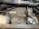
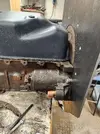
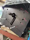
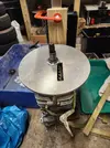
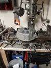
I'm in the middle of putting a fwd renault 5 turbo, with a espace gearbox in my lotus europa. The problem is the adaption of the bellhousing to engine.
I can make an adaptor plate, but the bellhousing on a espace is as big as the engine. Does anyone know of a smaller bellhousing that i can cut about and where i can get one
Reno fuego or 18 perhaps. Started to make steel bellhousing but a lot of work.
Thanks paul

20210919_125552.webp

IMG-20210621-WA0005.webp

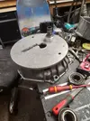
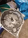
20230330_115104.webp
 
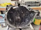
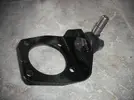
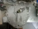
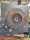
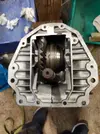
The Engine side is correct for any 13/1400 block. The top 6 bolts on the bellhousing to gearbox side, plus the shaft centres should align correctly. That leaves the lower half of the bellhousing. This may be slightly different, as basically The 385 (What this is) and 336 will interchange on any family 2 box (330-395)
I keep an NG1/3 input shaft bearing spigot, incase I get asked to do a rebuild on one, as getting them is a bit on and off. Making it fit will be a bit of a faff, building up and machining back, but the good news is that it only carries the radial load of the clutch input shaft, at 90 degrees to the shaft itself. It carries no axial load fore and aft. Happy enough to sell you the bits and if you find it won't work, before you've chopped them up, I'll refund you and you can send it back.
Hi steve,
Yep, I think I will give it a go.
I have 2 espace boxes, one with delivery milage as the car was made into a auto from renault and sat on the shelf for a long time.
So have 2 needle bearings already.
Don't think engine being straight up should be a problem, being converted to fuel
injection will lower height. Just need to fanny about with the baffled sump I got.
Did even think about putting a adaptor plate between box and bellhousing and mount bearing in a sleeve and welding that in.
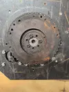
Do you think the 5 turbo 200 mm clutch flywheel will be ok, it's about 260mmm on the ring gear.The fuego clutch that fits the espace splines fits nice on that. The bearing I machined a copy from the 336 carrier and made that fit the 30mm espace bearing
Starter motor should be fine?
So , if you could let me know price and postage to Kent it would be much appreciated.
Rgds paul
 
I am positive the flywheel will fit in the Bellhousing, but I'll have a quick measure. I am wondering about the starter though. The smaller flywheel fitted to the R 5 Gordini turbo would likely solve those problems. When I turboed a R10 years ago I slotted the starter holes to get it working. I am sure we used a Volvo 340 starter for the solenoid position.
 
Hi Paul,

The issues with my installation included the starter motor, which made using the k-series bellhousing the easiest option for me. I'm not really familiar with the 5-turbo engine so maybe my advice there is less useful. There were many engine ancilliaries that ended up very adjacent to the chassis and I used a dummy plywood chassis Y-section to assess the fit before final installation. The engine needed a very small inclination to the vertical which is obviously dictated by the adaptor plate hole positions.

Some of the other problems were easier to resolve.

Gearbox output shafts no longer take the load from the suspension, a 'turnbuckle' micro-adjustable upper link does that job and the drive shaft is free to move in/out. These movements are very minimal because the rose joints in the link are positioned to replicate the drive shaft suspension pivot points and hence locus of motion. The rose joints attach to the adaptor plate at the inboard end, and to a bracket secured to the trailing arm by the 4 bolts attaching it to the uprights which have been helicoiled... because 54 year old threads... This increases the rear track by 20mm but can easily be compensated for in the suspension shimming and by trimming the rear wheel arch flange. The NG3 seals that run onto the output shaft are retained, and a useful bonus is that they don't leak!

Made a similar design but bespoke inner lower radius arm attachment bracket, easy enough

The rear gearbox mount is also bespoke and harks back to the 1980s with Ford Cortina engine mount rubbers

The gearshift needed painstaking adjustment but all do-able with a unique rear tube, brackets etc

I made a little gearbox from R/C model car gears to correct the speedo, guess a specialist could recalibrate the speedo head unit..?

The underlying reason for using the -99 box was to make use of a 25mph/1000rpm top gear, it being from diesel Espace donor. Torque from the vvc copes easily.

Hope this helps, not a 5 minute job, I spent about 4 months on it, off and on. Well worth the effort though in terms of performance, and also economy greatly improved.

Richard
Hi richard,
Any chance of some pics of the engine to gearbox. Looks like I need to attach a bellhousing to box and wanted to see how you managed that with a ng3 box. And very interested in the k series installation.
Rgds paul
 
Hi richard,
Any chance of some pics of the engine to gearbox. Looks like I need to attach a bellhousing to box and wanted to see how you managed that with a ng3 box. And very interested in the k series installation.
Rgds paul
Hi Paul, here's a few photos of the car as is. Bit dusty, I'm mid prep for a respray..

The engine-gearbox adaptor sets in metal the position of all the engine particularly the bits hanging off it, hence everything must be decided before starting the manufacture. The only 'hard point' is the crank and g/box input centreline. I made a dummy chassis from plywood to establish best angle of the engine to enable the standard exhaust manifold to be used.

Chassis mock-up showing position of oil filter and exhaust manifold.webp

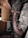
The two main conflicts were the manifold flange and the engine oil filter. They both needed a sandwich plate between the flange and the mounting faces on the engine to adjust the angle of the filter to horizontal and to tuck the exhaust closer to the engine block. These two established the angle of the engine to vertical. The dummy chassis was an essential aid and only took a couple of hours to put together.

The sandwich plate was made of 16mm ally plate. It needed to be as thin as practical because the depth of the MGF housing was 'longer' than the NG3 one and I wanted to use the standard gearbox input shaft. Even so the MGF housing needed material machining from both the engine flange and the gearbox flange. The milling machine worked overtime. The plate was designed to provide the inner mounting for the suspension upper link and also the exhaust silencer mount, plus the bearing and seal that normally sit in the Renault housing. The feed and exit for the silencer are the same end and the engine-silencer pipe does a tour of the engine bay to get there. I prioritised effective silencing and retaining the luggage box. The clutch release mech is MGF, the pressure plate MGF, but the friction disc Fuego to mate with the gearbox obv.

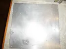
Establishing the bolt centres was a game. Everything relates back to the drive axis. I made a template from a piece of scrap 4mm ally, see following pic. The hole approx in the middle is the drive axis, the other 4mm ones relate to either the MGF housing or the NG3. I clamped the plate to each of the gearbox and bellhousing in turn, using a series of bespoke centre punches that were a close fit in the threaded holes to mark the position of the holes for the template [I used the NG3 housing with the seal/bearing 'bulge' around the input shaft machined flat]. The final assembly needed the use of several cap head screws machined to a more compact head size to make it all fit. The milling machine was very handy for accurately drilling the final adaptor plate. The care was worthwhile, it all fitted together first time, definitely a demonstration of the 6Ps!

SAM_0126.webp

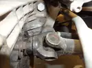
The inner attachment point for the upper radius arm can be seen peeking out from behind the drive shaft UJ in the photo below, also the gearshift tube. The pivot points for the upper radius arm replicate those of the UJs in the drive shaft, so no 'plunging' of the shaft relative to the spline occurs. No need for the dreaded roll pins either.SAM_0124.webp
 
Last edited by a moderator:
That looks like the Ford twink bellhousing which is much longer than the Renault item.
It is longer, but much milling machine action sorted that problem. The clutch friction plate can also be fitted either way around, offering a longer spline length in one direction. Not needing a flywheel spigot bearing also makes the whole thing easier to achieve
 
It is longer, but much milling machine action sorted that problem. The clutch friction plate can also be fitted either way around, offering a longer spline length in one direction. Not needing a flywheel spigot bearing also makes the whole thing easier to achieve
Hi richard,
How did you get the u/js to fit ng3 box. Thought they took cvs, which I will be using.
 
Hi richard,
How did you get the u/js to fit ng3 box. Thought they took cvs, which I will be using.
Hi Paul, they simply slide onto the shaft, being the same spline tooth count and profile. No roll pin. I debated whether to retain the drive shaft as the upper radius link, but since the adaptor plate offered potential for a very solid rose jointed upper link mount very adjacent to the shaft, it was possible to avoid the need for the splines to plunge in and out as the suspension moved by replicating the locus of movement of the pivots. This strategy steps the driveshaft and therefore the track width out by 10mm per side, needing spacers at the forward trailing arm bush and a longer lower radius arm to compensate. I also shaved the inner wheelarch return GF to give it a bit more room, it doesn't contact.

The big upside is leak free driveshaft seals.. not to be sniffed at, Europas almost always 'mark their territory'.

Using a CV would be possible, but then the drive shafts need changing, seemed a harder job to me, YMMV.
Hi richard, thanks for the info, would you have a picture of the plate that takes the ng3 needle bearing and the cut out for the crown wheel. As it looks I might be making a plate very similar.
Thks paul
 
Hi richard, thanks for the info, would you have a picture of the plate that takes the ng3 needle bearing and the cut out for the crown wheel. As it looks I might be making a plate very similar.
Thks paul
Hi Paul, I did all this 10 years ago, and because it was relatively much more involved compared with most of the stuff the Europa group were asking questions about, I never imagined anyone would want to go down the same route. Long way of saying there's no photo. What I will say is that because it was the diesel Espace the NG3 came from, the crown wheel of the NG3 is nearly the smallest in the NG3 range, the tooth numbers being 9:29. This means the cut out required is shallow, from memory it was less than the 16mm plate thickness, therefore the plate was simply milled to clear.

The trickier part was the needle roller support. It was, IIRC, an additional piece of ally bar having previously been machined to take the bearing. Correct alignment with the adaptor plate was achieved via the jig plate [see earlier photo]. The adaptor plate was drilled oversize to accept the bearing holder, which was ultimately secured with high strength Loctite. Hope that makes sense.

BTW, whilst looking for a photo I came across this one of the outer radius arm to trailing rose joint and bracket. It's all very tight hence the reduced head and built-in 'spanner flats' needed.

DSCF0008.webp

Cheers, Richard
 
Hi Paul, I did all this 10 years ago, and because it was relatively much more involved compared with most of the stuff the Europa group were asking questions about, I never imagined anyone would want to go down the same route. Long way of saying there's no photo. What I will say is that because it was the diesel Espace the NG3 came from, the crown wheel of the NG3 is nearly the smallest in the NG3 range, the tooth numbers being 9:29. This means the cut out required is shallow, from memory it was less than the 16mm plate thickness, therefore the plate was simply milled to clear.

The trickier part was the needle roller support. It was, IIRC, an additional piece of ally bar having previously been machined to take the bearing. Correct alignment with the adaptor plate was achieved via the jig plate [see earlier photo]. The adaptor plate was drilled oversize to accept the bearing holder, which was ultimately secured with high strength Loctite. Hope that makes sense.

BTW, whilst looking for a photo I came across this one of the outer radius arm to trailing rose joint and bracket. It's all very tight hence the reduced head and built-in 'spanner flats' needed.

View attachment 220291

Cheers, Richard
Hi richard,
This what I'm planning to use, plate on fwd 5 engine which takes care of the starter as the bellhousing will be a mk1 r5 and that has a smaller flywheel. On the other end will be a plate bolted to the ng3 and have the needle bearing in a housing welded to the plate. Will cut out for diff and seal with a cover.
Adapt a fork arm and carrier to fit.
It makes sense in my head?

IMG_20240918_133653773_MFNR.webp

20240909_153649.webp

20240909_153639.webp

20230524_161703.webp

20230524_191750.webp
 
Ok, bit of a change of direction, with steve swans help I'm now using a R17 bellhousing. Much better size to work with.
Made a top hat bush to take the needle bearing from the ng3 gearbox. 10mm alloy plate cut to take bush. Bellhousing fixed to plate. New plate made for engine side from 10mm plate which turned out to be not enough to get bearing clearance. So got another piece of plate alloy but it's 25mm thick. A friend of mine gave me the plate which he cut with his water jetter. So hopefully it will be going back to him to shape.

20241014_154339.webp

20241014_150304.webp

20241017_183634.webp

20241017_185046.webp

20241018_130636.webp

20241018_130642.webp

20241018_130707.webp

20240912_130415.webp
 
Morning steve,
As you can see, making some progress.
Waiting for my friend to jet the plate out.
10mm plate was not enough clearence for the bearing. The Ali plate is too thick, but with the hole in the middle I have access to a big lathe to machine to size. One problem is the 13mm dia bushes for the plates alignment. Can you buy them or have I got to make them.
Rgds paul
 
Hi everybody,
Gearbox alloy plate fitted now and all coming together. Just looking at other parts and noticed that the cj3 engine I'm using has rocker gear supports are not as meaty as a turbo 5 head. I'm using all turbo parts, head etc. But I haven't got the rocker gear. Has anyone got one spare I could buy, thanks paul
 
Back
Top