MakeEverything
Active Member
Following various philosophical conversations, I thought I would go back and see if I can justify why I have made certain decisions through the life of the project, and to verify that I have made correct (or incorrect) decisions so far before finalising the car and committing to power tuning and the associated effort. So I bought some more books to verify and validate these decisions based on the theory that I had already read when looking at “Hot Rodding” but have lost / sold / given away the books and material I had. The new references are included here, and are listed below in a bibliography. (Dave, try and stay awake!!)
Starting with a presumed ‘standard’ J7R engine (HFC), I will try and list the modifications and the reasons for keeping / changing them.
Inlet Manifold & TB
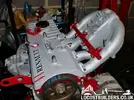
The inlet that came with the car (on the old 2.2 engine) worked ok, fitted in the engine bay, had equal length runners of about 330mm. The optimal length runners for supercharged inlets is 300-330mm. The diameter of these runners should be 0.87-0.95 of the inlet valve diameter. Mine are 35mm, which is 0.8 but I can’t change this at the moment. (Bell, 2002). How many of us know that the inlet runners are more restrictive than the TB?
I have now removed the nitrous system, until the car is set up and running without spikes in the AFR through the rev range. Maybe it will be put back on later….
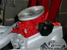
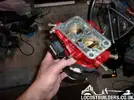
The Throttle body I have used is the one that came with the car. It’s a progressive twin butterfly WEBER throttle body, but I’m not sure what its off. The first stage butterfly is smaller than the main one, which should give me better throttle control at low speeds. (Bell, 2002) The secondary (Larger) butterfly plate starts to open when the primary is open at 50%. I didn’t measure these at the time, but preferred the idea of more throttle control at lower speeds so stuck with it. I had to replace the TPS for a standard generic unit as the one I had on it was toast (Possibly another reason I couldn’t get it to run properly with the 2.2 and a turbo).
Supercharger & Intercooler
When I had my old mini, I had planned to carry out the same exercise on that (before my acquired knowledge of EFI), and mount the Eaton M45 supercharger to that. This is a common modification to classic minis, however the costly kits including shed made brackets and inlets put me off of buying a standard kit. So, when we moved, the charger came with me and stayed in the box until I ripped out the 2.2 engine from the kit car.
Now, I had to do lots of research to check that this particular supercharger was up to the job. I had downloaded the supercharger map from the Eaton website and started from there. (Superchargers, 2012).

Getting the pulley off was a challenge. The fitting process must use a heated pulley on a cold shaft to get them on so tight, and it took some brute force and ignorance from an old acquaintance familiar with these age old techniques, to get it off. Thanks Digger. :05.18-flustered:
So, next I needed to calculate the pulley size that I needed. What dictated this was the output I needed from the supercharger to give me a safe boost level, within the capability of the MAP sensor on the ECU. I know that the pressure ratio is 1.36 (Calculation below), and I calculated that the engine consumes approximately 301.99CFM (21.13 lb/m or 513.084m?/hr) which is the flow into the supercharger.
CFM= L x RPM x VE x Pr
5660
Where; L = Engine Capacity (1.995L)
RPM = Maximum Engine Speed (7000rpm)
VE = Engine Volumetric Efficiency (90%)
Pr = Pressure Ratio
(1CFM x 0.07 = 1lb/m)
(Pressure Ratio = Bp+Ap)
Ap
Where; Bp = Boost Pressure (5.3psi)
Ap = Atmospheric Pressure (14.7psi)
Referencing this against the supercharger map, we can see that this (513.084m?/hr) takes us into the 50% efficiency island, 17% less than peak and that the supercharger needs to spin at 14,000rpm to meet this output. (Bell, 2002) (Superchargers, 2012).
So I now know how fast the supercharger needs to turn. I know that the crank pulley is 120mm, so i played with supercharger pulley sizes to find 70mm. This gives me a ratio of 1.71. According to (Bell, 2001), it seems I may be slightly underpowered in this ratio;
Required Ratio = Supercharger RPM @ Desired Airflow
Internal Gear Ratio x Engine Redline RPM
Therefore; 14,000
1 x 7100 = 1.97.
Transposing this using my actual ratio (1.71), my supercharger will spin at 12,141, producing 460m?/hr, a deficit of 53m₃hr (31.244CFM).
This is an oversight on my part, however I am governed by the size of pulleys available, and need to factor in that I am using an intercooler that would not normally be needed in my installation because of the thermal efficiencies being quite high. I calculated that the maximum inlet temperature increase from the supercharger is 23.8?C, but effectively have a front mounted cooler in one of the side scoops;
Density Ratio = Original Absolute Temperature
Final Absolute Temperature
(Based on an ambient of 25?C – optimistic summer! And an intercooler efficiency of 75%)
Original Absolute Temperature = Ambient Temperature + (0.75 x Discharge Temp)
25?C + (0.75 x 23.8?C) = 17.85?C, an IMPROVEMENT of 7.15?C!
Therefore; 25?C + 23.8?C
25?C + 17.85?C = Density Ratio of 1.13
This means that the intercooler will achieve a gain of 13% more air molecules to the combustion chamber than without, assuming adequate airflow and surface area to achieve 75% efficiency.
So how do I know how much boost im going to produce? Truth is, im not entirely sure yet! This is the one area still fairly new to me, but referencing (Bell, 2001) again, I can calculate that;
Boost = PR x Atmospheric Pressure
Therefore;
1.36 x 14.7 = 19.9psig Boost. 1.1psig below the MAP sensor limit (in the ideal world…) and more luck than judgement!! I was aiming for 17 originally!
And cue the critics! - though be advised, the calculations for superchargers are DIFFERENT to turbochargers, as the SC makes boost at low RPM with different thermal efficiencies.
Bibliography
Bell, A. G., 2002. Forced Induction Performance Tuning. 3rd ed. California: Haynes Publishing.
Bell, C., 2001. Supercharged! Design, Testing and Installation of Supercharger Systems. Cambridge, MA: Bentley Publishers.
Superchargers, E., 2012. M45 Superchargers. [Online]
Available at: http://www.eaton.com/Eaton/Products...utomotiveAftermarket/Superchargers/PCT_221788
[Accessed 2009].
Starting with a presumed ‘standard’ J7R engine (HFC), I will try and list the modifications and the reasons for keeping / changing them.
Inlet Manifold & TB
The inlet that came with the car (on the old 2.2 engine) worked ok, fitted in the engine bay, had equal length runners of about 330mm. The optimal length runners for supercharged inlets is 300-330mm. The diameter of these runners should be 0.87-0.95 of the inlet valve diameter. Mine are 35mm, which is 0.8 but I can’t change this at the moment. (Bell, 2002). How many of us know that the inlet runners are more restrictive than the TB?
I have now removed the nitrous system, until the car is set up and running without spikes in the AFR through the rev range. Maybe it will be put back on later….

The Throttle body I have used is the one that came with the car. It’s a progressive twin butterfly WEBER throttle body, but I’m not sure what its off. The first stage butterfly is smaller than the main one, which should give me better throttle control at low speeds. (Bell, 2002) The secondary (Larger) butterfly plate starts to open when the primary is open at 50%. I didn’t measure these at the time, but preferred the idea of more throttle control at lower speeds so stuck with it. I had to replace the TPS for a standard generic unit as the one I had on it was toast (Possibly another reason I couldn’t get it to run properly with the 2.2 and a turbo).


Supercharger & Intercooler
When I had my old mini, I had planned to carry out the same exercise on that (before my acquired knowledge of EFI), and mount the Eaton M45 supercharger to that. This is a common modification to classic minis, however the costly kits including shed made brackets and inlets put me off of buying a standard kit. So, when we moved, the charger came with me and stayed in the box until I ripped out the 2.2 engine from the kit car.
Now, I had to do lots of research to check that this particular supercharger was up to the job. I had downloaded the supercharger map from the Eaton website and started from there. (Superchargers, 2012).

Getting the pulley off was a challenge. The fitting process must use a heated pulley on a cold shaft to get them on so tight, and it took some brute force and ignorance from an old acquaintance familiar with these age old techniques, to get it off. Thanks Digger. :05.18-flustered:
So, next I needed to calculate the pulley size that I needed. What dictated this was the output I needed from the supercharger to give me a safe boost level, within the capability of the MAP sensor on the ECU. I know that the pressure ratio is 1.36 (Calculation below), and I calculated that the engine consumes approximately 301.99CFM (21.13 lb/m or 513.084m?/hr) which is the flow into the supercharger.
CFM= L x RPM x VE x Pr
5660
Where; L = Engine Capacity (1.995L)
RPM = Maximum Engine Speed (7000rpm)
VE = Engine Volumetric Efficiency (90%)
Pr = Pressure Ratio
(1CFM x 0.07 = 1lb/m)
(Pressure Ratio = Bp+Ap)
Ap
Where; Bp = Boost Pressure (5.3psi)
Ap = Atmospheric Pressure (14.7psi)
Referencing this against the supercharger map, we can see that this (513.084m?/hr) takes us into the 50% efficiency island, 17% less than peak and that the supercharger needs to spin at 14,000rpm to meet this output. (Bell, 2002) (Superchargers, 2012).
So I now know how fast the supercharger needs to turn. I know that the crank pulley is 120mm, so i played with supercharger pulley sizes to find 70mm. This gives me a ratio of 1.71. According to (Bell, 2001), it seems I may be slightly underpowered in this ratio;
Required Ratio = Supercharger RPM @ Desired Airflow
Internal Gear Ratio x Engine Redline RPM
Therefore; 14,000
1 x 7100 = 1.97.
Transposing this using my actual ratio (1.71), my supercharger will spin at 12,141, producing 460m?/hr, a deficit of 53m₃hr (31.244CFM).
This is an oversight on my part, however I am governed by the size of pulleys available, and need to factor in that I am using an intercooler that would not normally be needed in my installation because of the thermal efficiencies being quite high. I calculated that the maximum inlet temperature increase from the supercharger is 23.8?C, but effectively have a front mounted cooler in one of the side scoops;
Density Ratio = Original Absolute Temperature
Final Absolute Temperature
(Based on an ambient of 25?C – optimistic summer! And an intercooler efficiency of 75%)
Original Absolute Temperature = Ambient Temperature + (0.75 x Discharge Temp)
25?C + (0.75 x 23.8?C) = 17.85?C, an IMPROVEMENT of 7.15?C!
Therefore; 25?C + 23.8?C
25?C + 17.85?C = Density Ratio of 1.13
This means that the intercooler will achieve a gain of 13% more air molecules to the combustion chamber than without, assuming adequate airflow and surface area to achieve 75% efficiency.

So how do I know how much boost im going to produce? Truth is, im not entirely sure yet! This is the one area still fairly new to me, but referencing (Bell, 2001) again, I can calculate that;
Boost = PR x Atmospheric Pressure
Therefore;
1.36 x 14.7 = 19.9psig Boost. 1.1psig below the MAP sensor limit (in the ideal world…) and more luck than judgement!! I was aiming for 17 originally!
And cue the critics! - though be advised, the calculations for superchargers are DIFFERENT to turbochargers, as the SC makes boost at low RPM with different thermal efficiencies.
Bibliography
Bell, A. G., 2002. Forced Induction Performance Tuning. 3rd ed. California: Haynes Publishing.
Bell, C., 2001. Supercharged! Design, Testing and Installation of Supercharger Systems. Cambridge, MA: Bentley Publishers.
Superchargers, E., 2012. M45 Superchargers. [Online]
Available at: http://www.eaton.com/Eaton/Products...utomotiveAftermarket/Superchargers/PCT_221788
[Accessed 2009].
Last edited by a moderator:


