There is more to life with TurboRenault.co.uk

Register a free account today to become a member! Once signed in, you'll be able to participate on this site by adding your own topics and posts, as well as connect with other members through your own private inbox!

19 Project Turbo Shed - sponsored by Bosch PWS850-125

I've gone with 50A because I had one laying around.
rofl.gif rofl.gif rofl.gif rofl.gif rofl.gif rofl.gif
Bodge logic at it's finest.
Then there’s another wire that goes to the alternator light exciter wire so the pump only runs when the engine is on, to stop it flattening the battery. There’s also a third wire which apparently is just for some sort of vauxhall specific diagnostic type shit. Obviously left unconnected.

Great info, duly noted for when I come to sort my leaking PS pump. Think I will do the same as you!


It's just not good enough mate, weddings, babies (congrats btw) but no fuel computer. Priorities!
 
Bodge logic at it's finest.

It's not a bodge! The 50A fuse will blow earlier than an 80A one would, let's call it a safety upgrade ;)

I'd actually like to put a clamp meter on it and see how much it pulls, I find it hard to believe it gets close to 50A, let alone 80A. The fact that the 50A fuse hasn't blown (yet) suggests it doesn't.
 
Picked up a set of ph2 clio 172 leather/alcantara seats recently. Bloke locally was stripping out a car and fitting buckets as a track toy and gave me these seats for free.

Conveniently the pitch between the rails is the same on the clio seats as on the 19 so just had to modify the 19 seat runners to fit. That basically entailed stripping the runners apart and drilling new holes and welding new nuts on the inside. No photos of that as my camera decided to corrupt its card but let's just say it was a total ballache and leave it at that.

DSC07769.webp
DSC07768.webp

Not decided if I like this yet. I did want to keep the original hideous seats but the problem is that they're just so soggy and unsupportive. Not nice to sit in at all.

Suppose I can chuck some seat covers on. These have caught my eye

s-l500.webp
Or maybe these
s-l1600 (1).webp


Ooooooh baby yeah.
 
Speaking from experience there @DaveL485
No because i'm not a million years old, I dont wear a tea cosy for a hat, I dont wear tartan zip-up bootie slippers and I havent been drawing my pension since the turn of the century, therefore, I do not have god awful seat covers that make my rear end look like I got run over by knobbly road roller.
 
Took the shed to the TurboRenault rolling road day at Dynodaze in Nuneaton the other week. Behaved itself all day, did a couple of runs and returned home good as gold.

20180331_092409.webp
20180331_100609.webp
19meg240bhp281ft.webp

The result:

turboshedprintoutcropped.webp

Not bad!

After discussion, it seems there's growing consensus that the 280ft.lb torque suggests that the donor car might have been mapped.
 
Alright chaps, been busy.

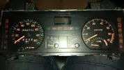
Having got the Arduino/stepper motor speedo and tach working, I decided that I wasn’t happy with them. I didn’t like the movement and I just like originality. An OLED screen for a odometer wasn’t that. Also, @DaveL485 gave me a 21T instrument cluster because I wanted the gimmicky boost gauge built into the rev counter.

IMG_20180331_174834.webp

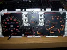
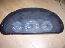
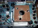
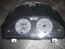
The 21T has the digital trip computer which seems to be identical to the R19 16v one and the cluster given to me by Dave is a Veglia unit. R19s got both Veglia and Sagem clusters (and some povo models had Jaeger). Interestingly, these Veglia clusters are completely modular. The white casing (either analogue or digital fuel gauge) is I think common. All of the gauge mechanisms and faces are the same, you can just pluck them out and swap them between versions. Typically though the cluster fitted to my R19 was Sagem. Therefore the tacho/boost gauge from the 21T could not be fitted to my 19 cluster. So I obtained an analogue fuel gauge version Veglia R19 cluster and swapped the 21T gauges into it. The clusters just have different fascias and a different front screen clipped on depending on what model they’re fitted to and also some slightly different link wires on the mylar PCB depending on whether it has the oil pressure function, stuff like that.

100_7874.webp

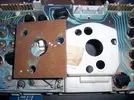
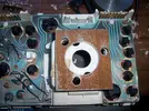
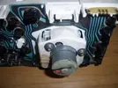
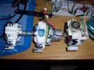
At this point it's still got a cable driven speedo, I need to make it work from the ABS sensor. For this I started out with the speedo head from a mk1 Punto. These use a Veglia speedo too, except on some models, instead of a cable going into the back, it has a little motor and a control board that takes a 12V square wave from a gearbox sensor and runs the motor to the appropriate speed. The barrel odometer and trip counter are mechanical in the same way as a cable driven version.

100_7864.webp
100_7865.webp

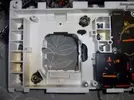
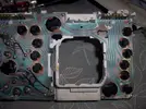
So a bit of dremel modification to the R19 cluster rear housing to accommodate the motor and different mounting arrangement and it was in. Also needed a bit of small scale dremel modding to fit the trip reset mechanism from the R19 speedo to the punto speedo to put the trip reset button the right place. Pretty simple and from the front you’d never know anything had been changed.

100_7866.webp
100_7867.webp
100_7868.webp
100_7869.webp
100_7872.webp
100_7873.webp
100_7870.webp

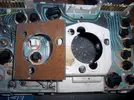
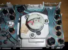
Later I decided that the Punto speedo was a bit shit, it works fine but it’s noisy, clunky and the linearity and repeatability are quite poor. So I found another type of electric speedo, typically fitted to certain late 90s citroens. I picked one up for a tenner from a 1.1 mk1 Saxo. The cluster is badged Jaeger but the mechanism bears more than a family resemblance to the Veglia speedos from the Renault and punto clusters.

100_7913.webp
100_7912.webp

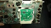
Straight fit to the Renault speedo fascia. This has an air core motor (like the fuel gauge, temp gauge and oil gauge) directly acting on the needle, and a separate stepper motor arrangement to drive the odometer and trip. All controlled by a little neatly integrated PCB on the back. Works the same, 12v variable frequency square wave input to drive it.

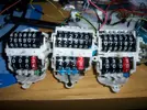
Quick comparison shots: left to right R19/21, punto, saxo

100_7914.webp
100_7915.webp
100_7916.webp

Had to chop out pretty big chunks of the back casing to fit, but fit it does. Really responsive and accurate/repeatable too. Nice, 10/10 good work Jaeger/Veglia.

100_7917.webp
100_7918.webp
IMG_20180530_210709.webp


I know what you’re thinking and you’re right, this is what I should have done in the first place.
 
So the speedo worked from an arduino feeding it pulses


That's the punto speedo, you can hear the racket it makes.

To feed the speed pulses to the speedo I need to use the same ABS sensor and VR conditioner setup I was using previously to get a 5V square wave. However the frequency of this signal is not what the electronic speedo control board is expecting to see so I needed to alter it. You can buy ‘speedo healer’ devices for motorbikes that do exactly this and by all accounts they work brilliantly for about £85. But they don’t work with VR sensors so I’d still have to condition the signal to feed into it and anyway, where’s the fun in buying?

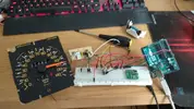
So again the Arduino would do the job. The commercial ones probably use an AVR or PIC to do the job anyway. Idea is to read the 5v square wave coming in, measure the frequency, apply a correction multiplier, then output a suitably frequency adjusted 5V square wave. Do this multiple times per second. I tried to do this entirely in software on the Arduino but couldn’t get it to work robustly. Not sure why, I think maybe because the FrequencyMeasure library I’m using to derive the incoming signal frequency basically spams interrupts and that screws up the loop timing. Somebody cleverer/more conversant with Arduino could probably make it work.
IMG_20180421_120009.webp

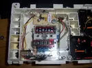
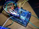
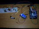
Anyway I resorted to extra hardware in form of a £10 AD9850 DDS module all the way from China. Basically, you send it a frequency command over a serial connection and it outputs a wave form. So the Arduino measures the frequency coming in, applies a multiplier to calculate the output frequency and then sends that frequency to the AD9850 which it generates until it’s sent a new frequency (which I do every 100ms). It can change from frequency to frequency without jitter and it can do it (theoretically) millions of times per second. It’s meant for generating radio frequencies really and I’m using it right at the very bottom end of its capability. Pretty amazing what you can get for a tenner these days.
100_7903.webp

100_7902.webp

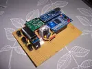
My finished board has an on-the-fly adjustable multiplier from 0.1% up to 999.9% in minimum of 0.1% steps. There are 3 buttons on my board – one to select the digit to change, one to increment and one to decrement. The multiplier is displayed on the OLED screen that was used as the odometer in my original stepper speedo. Yeah, way over the top but whatever. Multiplier is saved to EEPROM 10 seconds after a change and the screen turns off 10 seconds after any button press. It’s a bit on the big side but could easily be shrunk down. At the moment it just sits nicely in the centre console cassette holder. Total cost probably in the region of £45 (including the VR conditioner).
100_7905.webp

So anyway, this thing puts out a 5V square wave, then a basic signal transistor level shifts this to the 12V square wave that the punto speedo control board expects to see.

This is with it being fed a constant 100Hz signal, then adjusting the multiplier using the board


I know from calibrating my previous speedo that around 40000 ABS sensor pulses = 1 mile. Testing the Saxo speedo before pulling it apart it was 225Hz = 100mph. So initial multiplier was set to 14.8% and final adjustment on the road took it to 15.1% as spot on.

Code below in case anyone comes browsing along and wants to do something similar.

/*

Speedo Healer by Neal Wright 2018.

Uses FreqMeasure library from FreqMeasure Library, for Measuring Frequencies in the 0.1 to 1000 Hz range, or RPM Tachometer Applications
and AD9850 library from Arduino Projekte

*/

#include <Bounce2.h>
#include <EEPROMex.h>
#include <SPI.h>
#include <Wire.h>
//#include <Adafruit_GFX.h>
#include <Adafruit_SSD1306.h>
#include "FreqMeasure.h"
#define button_increase 12
#define button_decrease 11
#define button_select 10
#define OLED_RESET 4
#include <AH_AD9850.h>
//#define NUMFLAKES 10
//#define XPOS 0
//#define YPOS 1
//#define DELTAY 2
Bounce debouncer1 = Bounce();
Bounce debouncer2 = Bounce();
Bounce debouncer3 = Bounce();
AH_AD9850 AD9850(7, 6, 5, 4);
Adafruit_SSD1306 display(OLED_RESET);

const int UpdateInterval = 100;
unsigned long PreviousMillis = 0;
unsigned long buttonMillis;
unsigned long changemillis;
float outfrequency = 0;
float frequency = 0;
double sum=0;
int count=0;
int noInputCount = 0;
int increment = 1;
int multiplier = 1;
int multiplier2 = 1;
float percent;
int ones;
int tens;
int hundreds;
int thousands;
int ForceMulti = 0;
int memstatus = 1;
String MultiRead;

void setup(void)
{
if (ForceMulti == 0) {
MultiRead = String(EEPROM.read(0))+String(EEPROM.read(1))+String(EEPROM.read(2))+String(EEPROM.read(3));
multiplier = MultiRead.toInt();
multiplier2 = multiplier;
}
Serial.begin(9600);
display.begin(SSD1306_SWITCHCAPVCC);
FreqMeasure.begin();
AD9850.reset();
delay(1000);
AD9850.powerDown();
pinMode(8, INPUT_PULLUP);
pinMode(button_select,INPUT_PULLUP);
debouncer1.attach(button_select);
debouncer1.interval(5); // interval in ms
pinMode(button_increase,INPUT_PULLUP);
debouncer2.attach(button_increase);
debouncer2.interval(5); // interval in ms
pinMode(button_decrease,INPUT_PULLUP);
debouncer3.attach(button_decrease);
debouncer3.interval(5); // interval in ms

}

void loop() {
if (multiplier != multiplier2){
changemillis = millis();
memstatus = 0;
multiplier2 = multiplier;
}

if(memstatus == 0){
if(changemillis+10000 < millis()){
EEPROM.write(0,thousands);
EEPROM.write(1,hundreds);
EEPROM.write(2,tens);
EEPROM.write(3,ones);
memstatus = 1;
}
}
multiplier = constrain(multiplier,1,9999);
unsigned long currentMillis = millis();

if (currentMillis - PreviousMillis >= UpdateInterval) {
PreviousMillis = currentMillis;
count = 0;
sum = 0;

while (FreqMeasure.available()) {
sum += FreqMeasure.read();
count++;
}

if (count) {
frequency = FreqMeasure.countToFrequency(sum / count);
noInputCount = 0;
}
else if (++noInputCount == 2)
frequency = 0;

outfrequency = ((multiplier * frequency) / 1000);
Serial.println(outfrequency);
AD9850.set_frequency(outfrequency);
}


debouncer1.update();

if ( debouncer1.fell() ) {
buttonMillis = millis();
if(increment == 1)
increment = 1000;
else if(increment == 1000){
increment = 100;
}
else if (increment == 100){
increment = 10;
}
else if (increment == 10){
increment = 1;
}
}

debouncer2.update();

if ( debouncer2.fell() ) {
multiplier = multiplier + increment;
buttonMillis = millis();
}

debouncer3.update();

if ( debouncer3.fell() ) {
multiplier = multiplier - increment;
buttonMillis = millis();
}

if(buttonMillis+30000 > millis()){
thousands = ((multiplier/1000)%10);
hundreds = ((multiplier/100)%10);
tens = ((multiplier/10)%10);
ones = ((multiplier/1)%10);
display.setTextSize(3);
display.setTextColor(WHITE);
display.clearDisplay();
if(increment == 1000){
display.drawLine(4, 28, 20, 28, WHITE);
}
else if(increment == 100){
display.drawLine(24, 28, 40, 28, WHITE);
}
else if (increment == 10){
display.drawLine(44, 28, 60, 28, WHITE);
}
else if (increment == 1){
display.drawLine(72, 28, 88, 28, WHITE);
}
if(multiplier > 999){
display.setCursor(5,0);
display.println(thousands);
}
if(multiplier > 99){
display.setCursor(25,0);
display.println(hundreds);
}
if(multiplier > 9){
display.setCursor(45,0);
display.println(tens);
}
display.setCursor(73,0);
display.println(ones);
display.setCursor(58,0);
display.println(".");
display.setCursor(100,0);
display.println("%");
}
else if(buttonMillis+30000 <= millis()){
display.clearDisplay();

}
display.display();

}
 
Getting the tacho working was pretty basic, no microcontroller trickery required. I’m using a circuit from the Megasquirt manual. It involves the coil from a standard 12v relay, a basic signal transistor and a couple of resistors.

tacho.gif

I gutted a flasher (or wiper?) relay and put the bits inside.

IMG_20180614_202453.webp
IMG_20180614_202517.webp

Being pulsed by the trusty arduino:


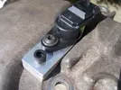
To generate a 2 pulse-per-crank-rev signal I’ve used a bosch hall sensor which seems to be a fairly standard part, used on Vauxhall, Ford, Volvo Alfa, all sorts. I’m powering the sensor from the same LM2940 5V voltage regulator that powers the speedo gubbins. These sensors are ‘active low with an open collector’ which means when there’s something metallic in front of the sensor it pulls the signal line to ground. When there’s nothing in front of the sensor, the signal wire floats. So, a 1K pullup resistor between +5v and signal makes sure that the signal stays high until forced low.

I mounted this in the pulley cover using some waterjet ally bits. This then directly reads the ‘spokes’ of the exhaust cam pulley. Conveniently there are 4 spokes on a 225 pulley which gives the required 2 pulses per crank rev, so no need to mess with Arduino to change the signal.
100_7875.webp
100_7876.webp
100_7878.webp
100_7879.webp
100_7881.webp
100_7884.webp


When the 5v signal from the sensor goes high, it switches on the transistor. This then allows a 12v feed into the relay coil. When the input goes low, the transistor switches off, the field in the coil collapses and sends a flyback spike out to the tacho which mimics the original ignition module pulse. Simples.

Couldn't fit all the crap inside the cluster this time so it's mounted on the back

100_7920.webp

Test drive on my private road:


So that's complete for now. To get the correct orange fascia for the fuel gauge, I'd need one from a phase 1 16v. But only the cabbies came with an analogue fuel gauge. And there were only 35-ish of those in the UK. So, might be unlucky there unless I can get one from abroad or from a different model.
 
Last edited:
I did have a few used ones kicking about, if i can find them you can have it for free. Lockwood do a replica one however will stand out like a dogs dick being bright orange
 
This is utterly ridiculous and brilliant.

I made something similar for the tacho to get the Adaptronic driving the OE rev counter but couldnt get it to work (from the ign3 output), I ended up having to reinstall the OE coil pack to make the rev counter work even though it now runs wasted spark!
 
Back
Top