There is more to life with TurboRenault.co.uk

Register a free account today to become a member! Once signed in, you'll be able to participate on this site by adding your own topics and posts, as well as connect with other members through your own private inbox!

19 Project Turbo Shed - sponsored by Bosch PWS850-125

That is crap, gutted for you

Sorry forgot I mentioned before, I have been using them since my old vag powered 5 many years back and was my 1st custom shaft. Used them quite a bit since so get a cheeky trade price......I would not pay £295+vat to be fair

DG
 
Awesome, read all 10 pages last night. Love the humour in between the in depth posts along the way, its also amazing how the Renault parts bin can cover so many bases to get this through with a little bit of jigging and poking to make them work.

Not on the same level as this but it reminds me of the Chamade 16V I converted to C1J many moons ago, more for buying such a cheap car and having most of the parts to hand to just do it.

Looking forward to reading more updates.
 
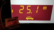
Right, so I need (or at least want) some way of telling how fast I’m going in this thing and as I’m trying to keep everything OE-looking I’d like to use the standard speedo to do it rather than bodging in the megane cluster or some aftermarket thing. I also want the tacho working.

Problem is, the original 19 speedo is mechanical, driven from a cable into the gearbox. But the megane gearbox has no cable drive. Also the 19 tacho is driven by pulses from the ignition module and won’t work with the coil-on-plug setup the 225 engine uses as standard. Solution = use the ABS sensor present on my scenic hubs to do the speedo job electronically with an Arduino. Similar arrangement for the tacho.

Luckily some much cleverer people than me have done most of the leg work to make this happen and put it on the net for others to benefit from. Gotta love the internet and the spirit of open source/homebrew project sharing. I owe this chap (and the guys whose libraries he in turn built on) a beer or two:

Arduino speedometer

Tl;dr ABS sensor wired to Arduino which is programmed to count pulses, do some maths and then drive a stepper motor to the relevant position.

I’ve basically copied the setup in the link above with a handful of tweaks and additions, then built it up in such as way that it all fits inside the Renault dash cluster.

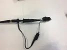
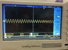
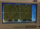
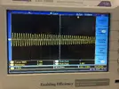
The first job for me to do was sort out myself the correct sensor input for it to work off. The clio/scenic ABS sensor is a VR (Variable Reluctance) sensor which means it outputs a voltage sine wave which increases with both frequency and amplitude as speed goes up.

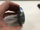
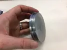
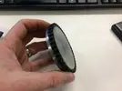
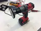
Few minutes on the lathe making test apparatus:
IMG_0599.webp
IMG_0600.webp
IMG_0601.webp
IMG_0602.webp
IMG_0603.webp
IMG_0604.webp

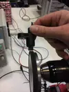
Spinning it at variable speeds:
IMG_0608.webp
IMG_0605.webp
IMG_0606.webp
IMG_0607.webp

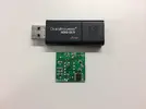
Since an Arduino can only use a 5V square wave on a digital input, this is no good to use as-is so the VR sensor output needs conditioning. There’s a little chip called the MAX9926 which is awesome for this job and is used in the newer versions of the Megasquirt ECU as well as commercial ECUs such as ME221 and probably others. It’s a SMD chip which is awkward for a ham fisted home DIYer like me to work with but again luckily for me various clever people have again been here before and done the hard work and produced neat little assembled standalone carrier boards for this chip (meant to plug into a Speeduino for crank TDC sensing) available fairly cheaply on ebay.

IMG_0619.webp

VR Sensor input one side, add 5V power supply and out comes your 5V PWM on the other side. Super super easy. What’s even better is that this chip is actually dual channel so this one tiny board can simultaneously process the signal for both the speedo ABS sensor and another sensor for the tacho.

TBC
 
Last edited:
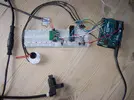
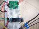
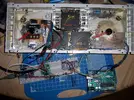
Prototyped up on breadboard with an Arduino UNO:

100_7672.webp
100_7673.webp

That all worked OK; spin the drill = needle moves and odometer counts up. Winning.

I'm using ubiquitous GM type steppers, I originally tried to use the ones I pulled off the megane’s cluster which from the datasheets have basically the same specs but for whatever reason I just couldn’t get them to play nicely.

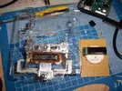
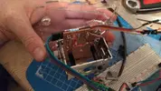
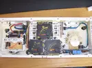
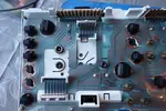
Now to mod the cluster. For info, the original speedo head is a spinning disc eddy current device and the tacho is a moving coil galvanometer. Fuel level, temperature and oil level are all air core motors. Gutted the speedo and tacho out to leave their respective casings to make mounting the dial faces in the exact same place easy, and fitted the steppers mounted to their own daughter boards.
100_7675.webp
IMG_20170809_215704.webp
IMG_20170809_215717.webp

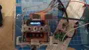
Still working. So far so good. Quick POST:


:)

Now want to fit all this into the dash cluster to keep things neat. To do that I transitioned to Arduino nano - essentially the same as an Arduino UNO but much much smaller and directly board mountable. These are chinese clones, about £3.50 each, ridiculous. I’m using one for speedo and one for tacho. I think theoretically one Arduino could possibly run both but let’s keep the code simple.

100_7676.webp

To integrate:

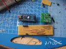
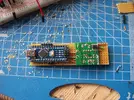
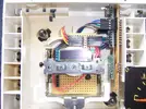
Made up a board to carry and directly connect and power the speedo arduino and the VR conditioner.

100_7677.webp
100_7678.webp

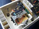
Fitted:

100_7680.webp
100_7679.webp

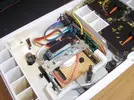
The tacho board just carries the other arduino and connecting pins. One wire between them to carry the sensor pulse from the second channel on the VR conditioner.

100_7685.webp
100_7686.webp
100_7687.webp

TBC...
 
POWER!!!

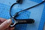
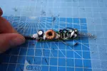
Arduinos have a couple of options for power supply - you can feed them 5v directly or they have a linear regulator on board for up to 12V. In theory you could probably just wire into the car’s 12V switched supply however it’s usually a shitty, noisy 12v (or rather 14V+), the regulators get hot at that level of input and there can be spikes to much higher than that. So instead I dug out an old phone charger that the micro USB plug was knackered on and recycled that for its board to do the voltage regulation and protection duties.

DSC07726.webp

These chargers commonly use basic switched mode regulation instead = minimal heat. Looks like some nice beefy smoothing/protection circuitry on this too. Ideal.:

DSC07709.webp

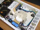
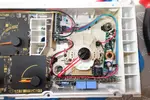
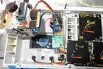
All wired in and self contained in the cluster.

DSC07725.webp

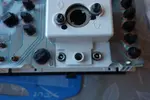
On the back, one barrel jack for switched 12V in, another two for each of the sensor inputs. 12V in jack is slightly different size and can’t be plugged into either of the sensor inputs (which would be a bad thing) accidentally :)

DSC07727.webp DSC07728.webp DSC07716.webp
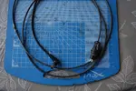
To go from the cluster to the ABS sensor connector in the wheel arch, I’ve cut up a front-to-back ABS loom from a mk2 clio to give me a waterproof moulded-on ABS plug with a plain 1.5 meter long cable attached. On the other end I've fitted a barrel jack plug to go straight into the cluster.

s-l1600.webp
DSC07729.webp

Test - connected up with the front jacked up, wheels off the ground.


might try to implement micro-stepping in the code to smooth the needle movement a little more. Also might leave the dial faces off as it looks cool :)

Still to do: to get the tacho working - waterjet a custom 8 tooth trigger wheel and weld it to the crank aux pulley, make up a mount for another ABS sensor or TDC sensor to read that trigger wheel.
 
Last edited:
WOW just WOW, the level of work you have put into that dash is awesome and i love it, honestly wish i had the time to pick up the skills to do similar. This is Awesome keep up the good work (y)
 
honestly wish i had the intelligence to pick up the skills to do similar.
Fixed that for you :D

Awesome stuff, I downloaded a stack of info on the Arduino kit to see if I could pick up the idea @r5gordini had about replacing the 21 fuel computer but....i'm quite a way off lol!

The message on the dash display made me laugh out loud hahaha
 
Fixed that for you :D

Awesome stuff, I downloaded a stack of info on the Arduino kit to see if I could pick up the idea @r5gordini had about replacing the 21 fuel computer but....i'm quite a way off lol!

The message on the dash display made me laugh out loud hahaha

@Chet T16 has done a lot of work on reverse engineering the trip comp, he knows how it works inside out at this point.
 
@Chet T16 has done a lot of work on reverse engineering the trip comp, he knows how it works inside out at this point.
Yeah pretty much. I started with reverse engineering the screen protocol with the intention of either sending additional data to stock screen or adapting a different screen to work with the stock computer. It makes more sense to just replace the whole thing.

There's just a couple of analogue inputs and two pulsed signals. I have it all recorded somewhere.

At one point I was sniffing the LCD data and displaying it on a webpage via wifi. I have no idea why.

I intend to get back to it (along with everything else...) _cdn.com_20170910_1b142d03e75eb43812cc56fe0a361539.webp

Sent from my SM-G925F using Tapatalk
 
Been having a bit of a rearrangement of the fuel system recently...

Ditched off my carefully crafted in tank regulator, non return arrangement
100_7391.webp

Went back to a normal return style system with regulator up front
100_7696.webp
100_7697.webp
100_7698.webp

That's a standard Bosch 3.5bar regulator in the cut off and capped end of a VW fuel rail. Pro level stuff yeah?

What was the evap vent line line from the tank is now being used as the fuel return line.

I've been getting a few miles on the thing in the local area. Drives fine. Really badly needs power steering though. I'm working on that.

Also I'd like a wideband lambda and AFR gauge as I'm paranoid.
 
Gentlemen, we have power steering!

Mixture of quite easy and total ballache.

I’m using a hydraulic mk1 scenic steering rack which of course bolts up to subframe perfectly what with it originally coming off this subframe (because the subframe itself is from a scenic). This wouldn't fit in the car as the high pressure pipe coming in from the right was nowhere near clearing the meg 225 the gearbox.
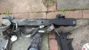
IMG_20171014_144205.webp

Just got to feed it hydraulic pressure. I looked at using a mechanical pump from a laguna or something like that, with the corresponding aux bracketry, however I didn't want to do that because reasons.

Other option was to use an electro-hydraulic pump. The saxo/106 pump (which I believe is just a generic off the shelf hydraulic power pack) is the one people often use in kit cars etc for retro fit PAS but these are not known for reliability, supply is getting scarce and it’s the wrong shape for me to fit anywhere in the space I have available.
Loads of other modern cars use electric pumps but most are controlled by CANbus. The handful of ‘dumb’ options include MR2 roadster, Vauxhall Astra G/H, Mercedes A class and I think early BMW minis. MR2 ones are rare, the merc ones are about £60 on ebay and not many of them available, the Astra ones are only about £20-25 and ebay is awash with them. Astra one it is.

Got one for £15 delivered, including the first bit of the pressure pipe and the isolating soft mounting cradle.
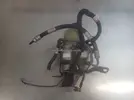
s-l1600.webp
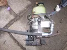
Built in reservoir and cooler loop not required with this. Happy days. Down the front corner by the headlight is a tight but suitable home for it.
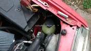
IMG_20171002_181352.webp

Modified the mounting bracket to have 3 points of attachment to the shell, nice and secure.
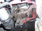
100_7707.webp

Now to get a hydraulic connection between pump and rack I had to modify the flared 10mm rigid pipe that comes out of the rack, to clear the back of the gearbox. I cut the bracket off, modified and re-welded. Then fitted a BSP threaded compression fitting to the bare pipe.
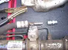
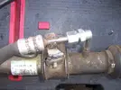
100_7703.webp
100_7705.webp

on the pump end there’s a similar rigid 10mm pipe and then a flexi bit. Cut the flexi bit off as I want all the pipework to run under the chassis rail so if I need to drop the subframe off with the rack attached (which I need to do to get the engine out) the pump can go down with it and no need to drain the system. Another compression fitting on the end of this.
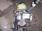
100_7721.webp

Both rigid ends with compression fittings:
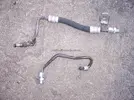
100_7720.webp

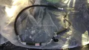
To join the pump and rack together needs a proper high pressure hose. I went to a hydraulics place near work - Hydraquip in Bristol. Great bunch of guys in there, helped me out no end with advice and suggestions over a handful of visits. They even have a friendly office doggo called Smudge. If you’re around Bristol and need any odd custom hydraulic hoses, that’s the place to go. Anyway in the end designing the pipe to make it remotely was tricky so I took away a selection of end fittings and a length of hose and cut/assembled to suit on the car with trial and error, marked up fitting orientations/rotations etc, then took it back to get the fittings swaged on.
IMG_20171030_104310.webp

I’ve made it in 2 halves with a connection that sits on the chassis rail which makes assembly easier as the fittings at each end are almost impossible to get to with the rack and pump in place. So the pump goes in with one half of the hose connected, the rack goes in with the other half and then they just get connected together in the wheel arch, pretty convenient.

Pump end
100_7722.webp

100_7727.webp
Rack end

100_7713.webp


The return line is just 10mm bore fuel/oil hose running across the front of the car on top of the intercooler.

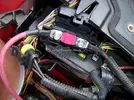
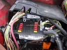
Running the pump is easy, It just has a chunky earth with a ring terminal that can connect straight up to my existing earth stud on the chassis rail. The +12V has a weird concealed spade terminal on it, I cut that off and crimped on another ring terminal. This goes via a mega fuse to my main 12V junction box on the bulkhead. According to Autodata that fuse is 80A in the Astra which seems a bit mad to me, I've gone with 50A because I had one laying around.
100_7723.webp

Tucks away in the main fuse box nicely.
100_7724.webp

There are 3 other small wires on an AMP superseal plug. One is switched 12v to wake the unit up with ignition on. Basically seems to be an internal relay. I connected this via a 10A fuse (replicating the Astra setup) and matching female superseal connector to what was the coil 12V feed on the original engine loom. Then there’s another wire that goes to the alternator light exciter wire so the pump only runs when the engine is on, to stop it flattening the battery. There’s also a third wire which apparently is just for some sort of vauxhall specific diagnostic type shit. Obviously left unconnected.
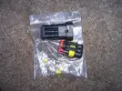
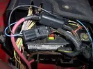
100_7728.webp
100_7729.webp

I might wire it up so I can override the alternator feed with a switch in the cabin so I can run the PAS without having the engine running.

Last thing – fluid. The Renault system runs the basic ATF/dexron type stuff but the Astra system uses ‘pentosin CHF 11S’ fluid. As far as I can make out, they don’t mix, but they’re not incompatible in terms of killing seals etc. My thinking is that it’s probably better to give the pump what it likes and let the rack lump it than the other way round, so in went the green pentosin stuff.
Works OK :)

Overestimated how much it would take to fill the system, didn't even take a whole bottle bottle!
100_7725.webp

Also fitted a powerflex polybushed dogbone to get rid of some of the engine movement.
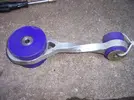
100_7726.webp
 
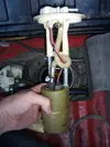
Just caught up on this thread after a long time away from it! Love the work you've done on the speedo, etc. My fuel computer project is somewhat stalled for the moment (Sorry @DaveL485 )
I used an Ariduino, much like you. Wrote my own code.
It's still in my Quadra, which has sat idle for many months now. Want to get back into it but struggling to get my A610 properly roadworthy first.
Andrew
 
Back
Top